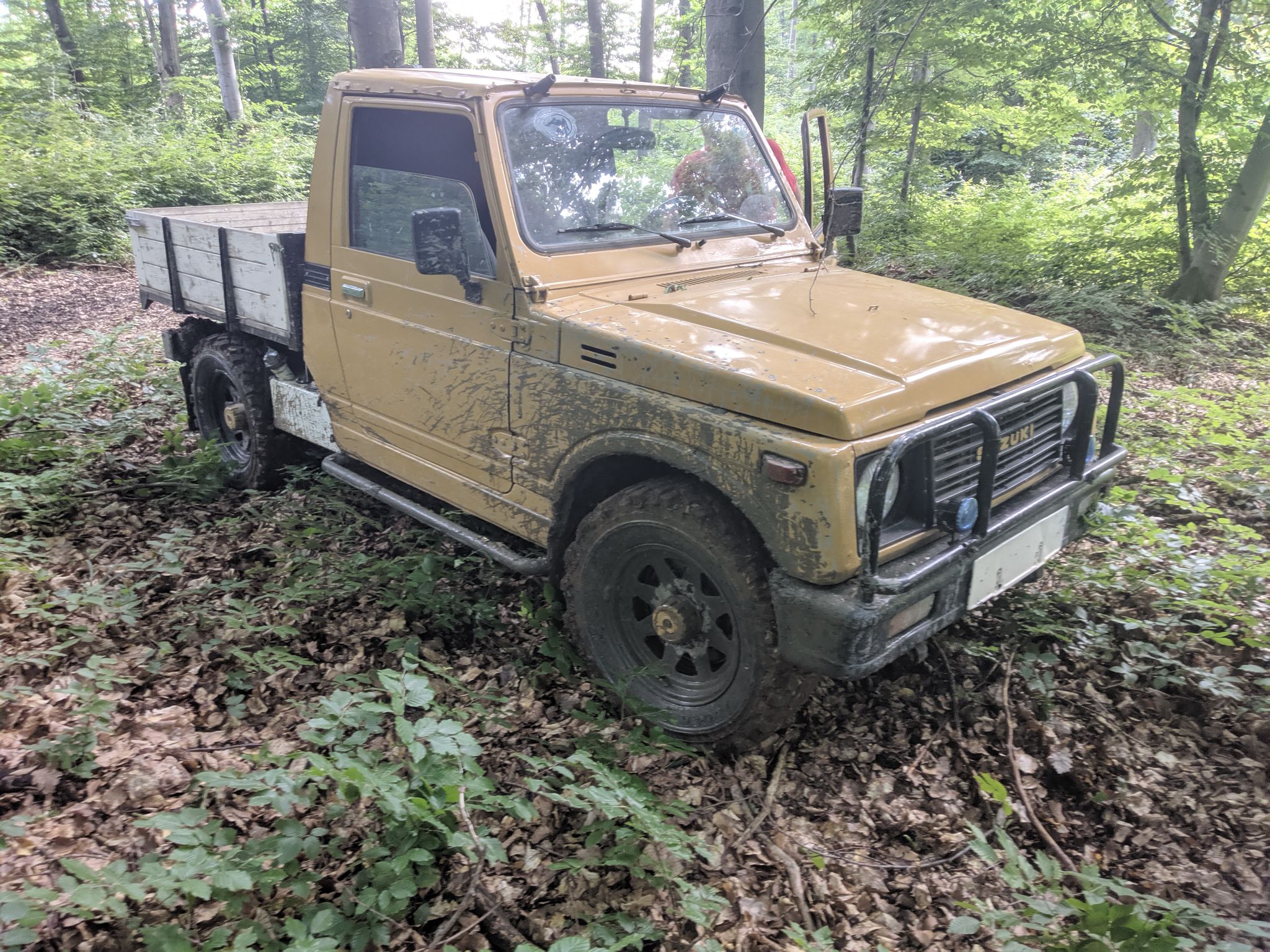

This particular car is used in a farm environment where it is used to haul cargo over short distances. This usage requires it to reliably crank and run well while cold.
Up until now the Pierburg 2e3 carburetor was used, this is one of the most common replacements in Czechoslovakia for the original complicated and unreliable Aisin 1320083001.
While this option is far superior to the original carb, it is still nowhere near as simple, flexible, and reliable as modern fuel injection. In this application the car spends a large amount of time
of time on choke, this choke is automatic and extremely aggresive. Both here and in it's original application it causes flooding and when cold the engine only runs on 2 cylinders.
A major side effect is extremely high fuel consumption, I estimate around a 50% drop in fuel consumption with EFI. Another major problem is the lack of power under 2300RPM, this complicates things offroad.
Goals of this upgrade are:
Improving cold states
Low RPM performance
Engine braking
Simplification of tuning
Increasing future options without major changes(Turbochargers, Superchargers, 1.6 swap etc...)
Learn tuning with TunerStudio and get better at wiring harnesses
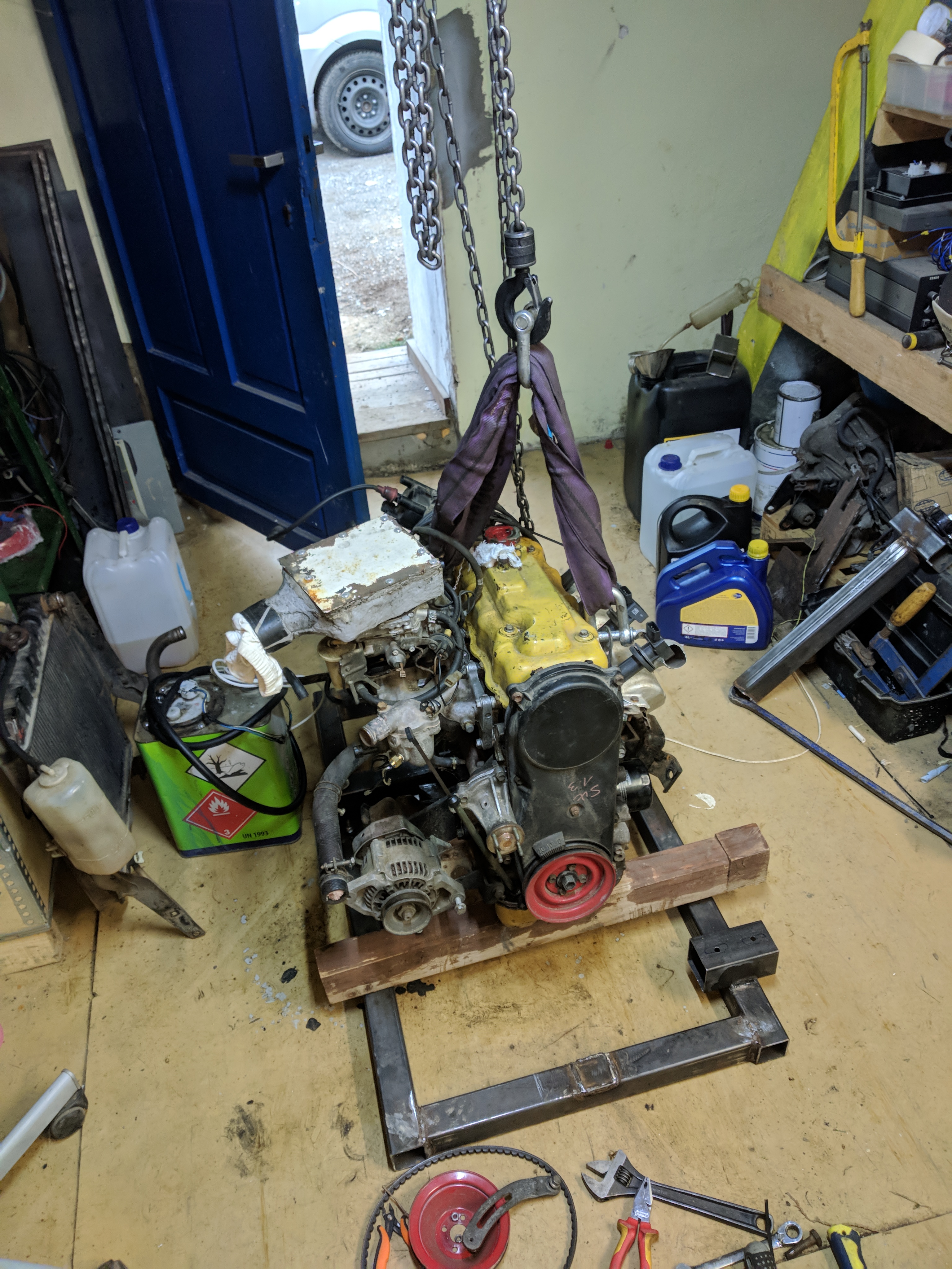
Before I start tearing into it, i have to pick and obtain the necessary parts
Key components are:
ECU
Sensors(Manifold pressure, Cam and Crank position, Coolant temperature, Air temperature, Throttle position, Wideband O2 sensor)
Fuel injectors and the fuel rail
Ignition coils
Throttlebody
Intake manifold that can accomidate multipoint fuel injection and a throttlebody
High pressure fuel pump
Power distribution box
Various materials for wiring
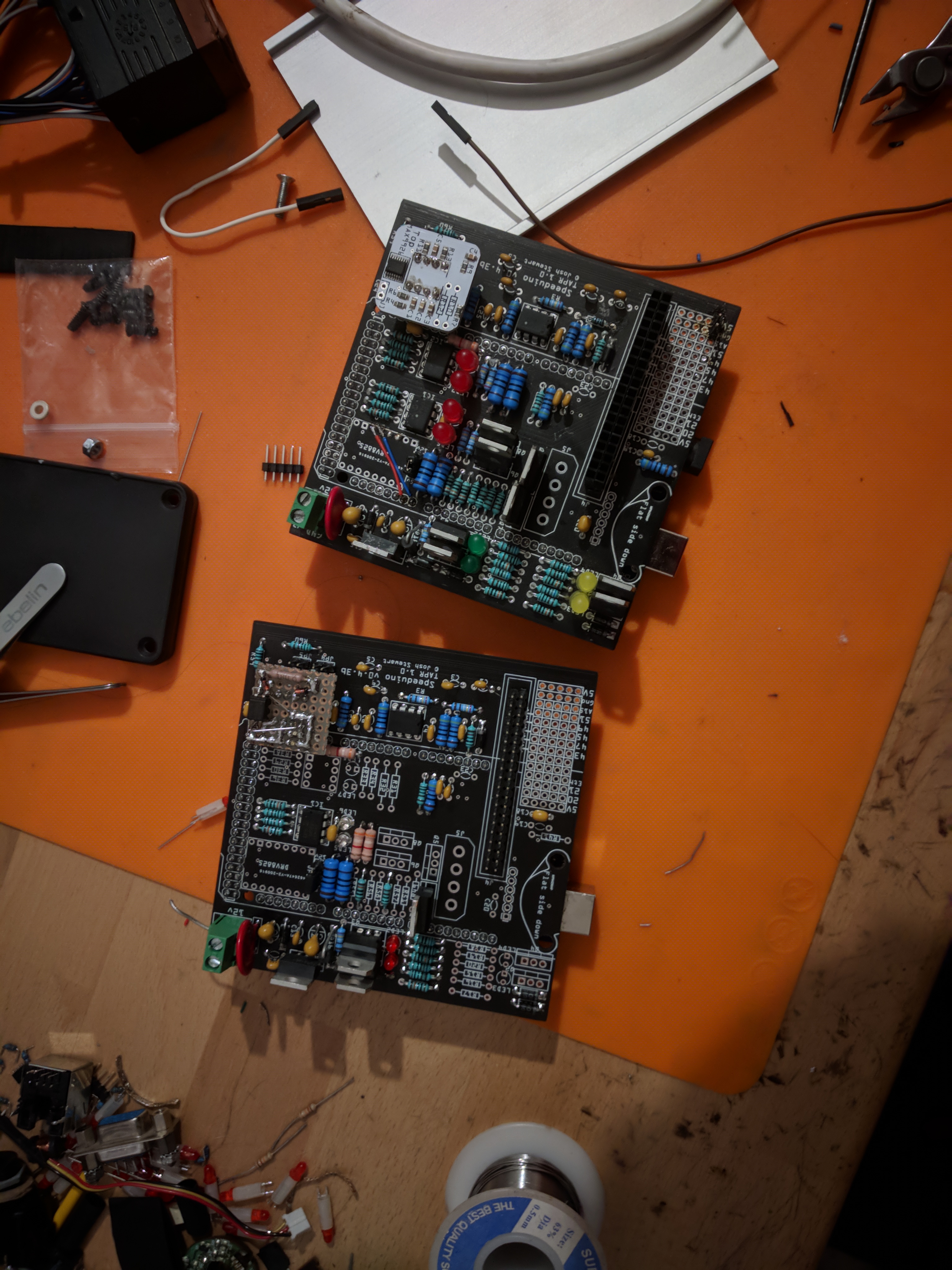
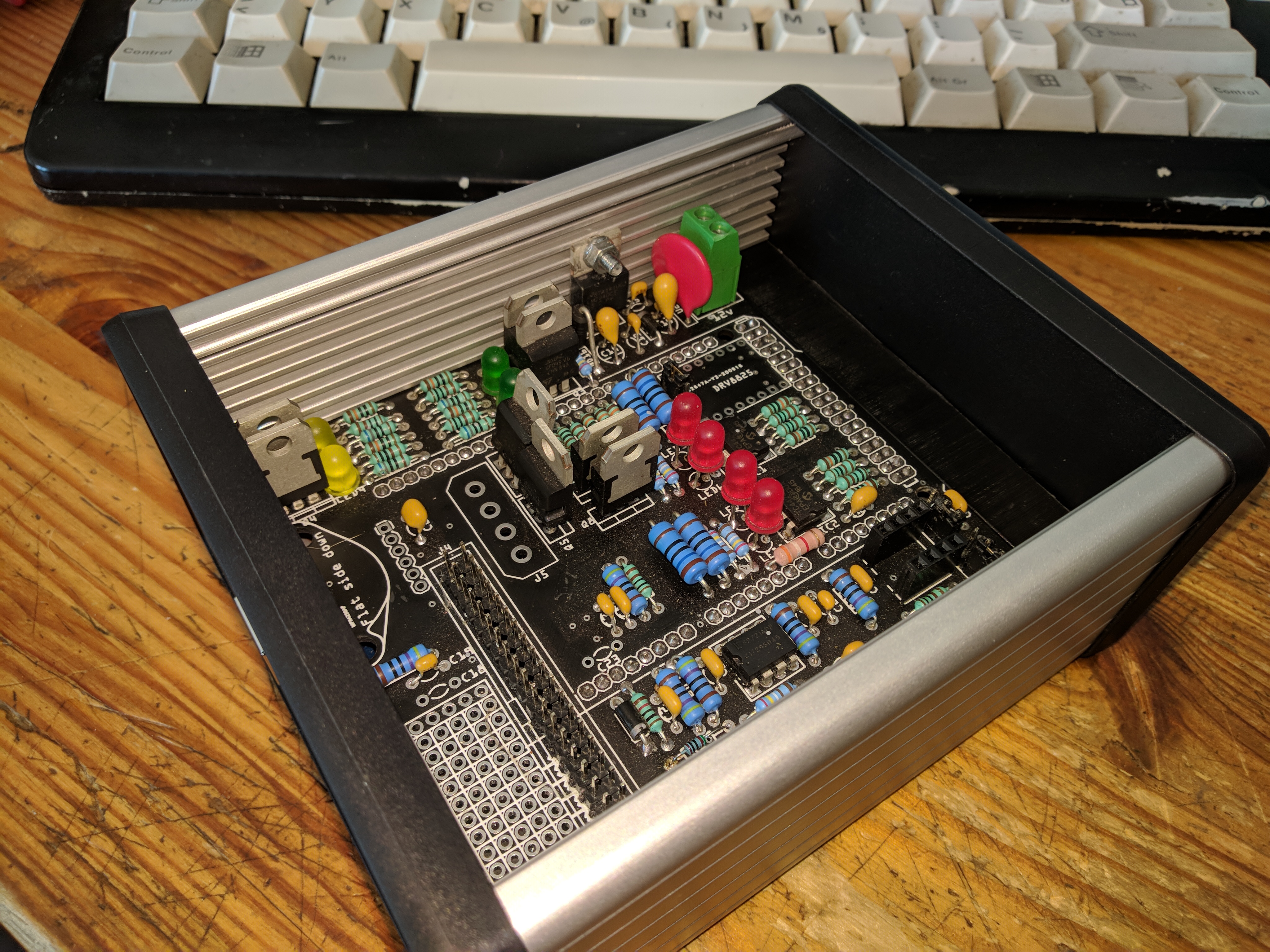
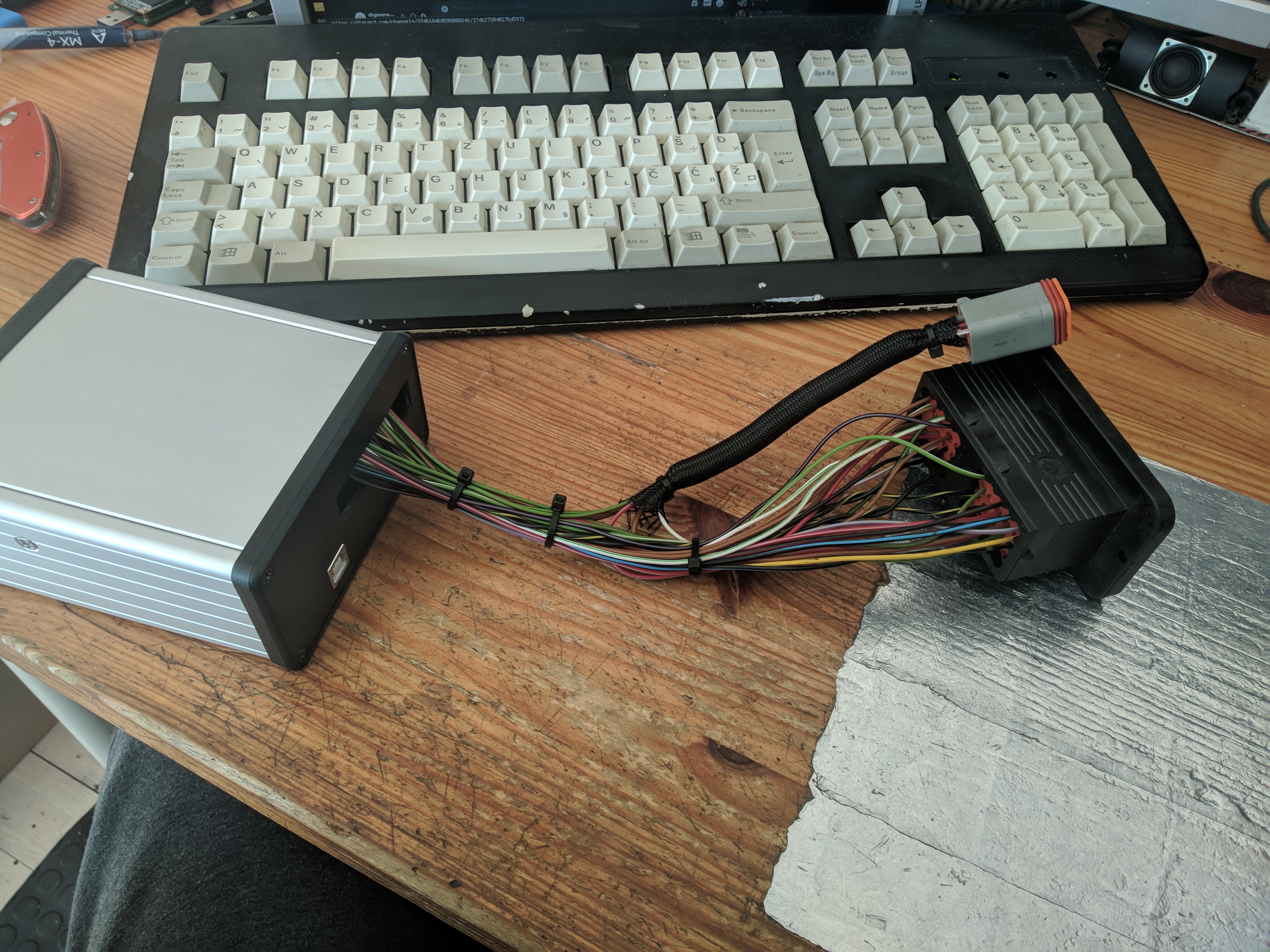
After evaluating the available options I settled for the Speeduino V0.4. It has all the features I want and fits in my budget.
Some of the required features are: 4 ignition and injection channels, external MAP sensor input, two coil idle valve control, external communication for a dashboard,
two VR position sensor inputs, external Wideband O2 input.
This particular ECU also has programable outputs making it easy to power the Wideband heater correctly.
It fits very nicely into the HAMMOND HM-1455N1202 extruded aluminium enclousure.
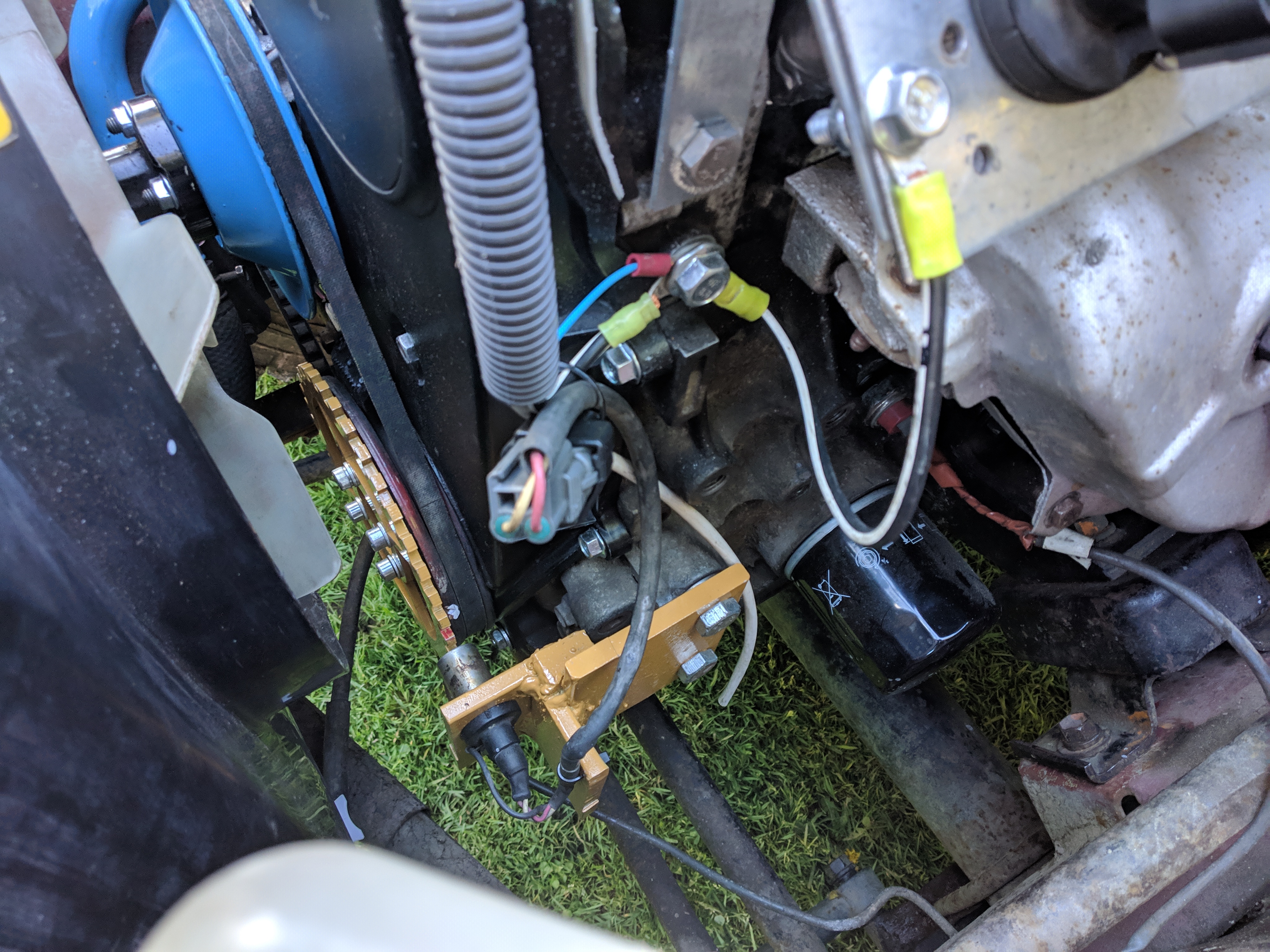
This injection system is a sequential setup, that requires per cylinder injectors, coils, and the camshaft position.
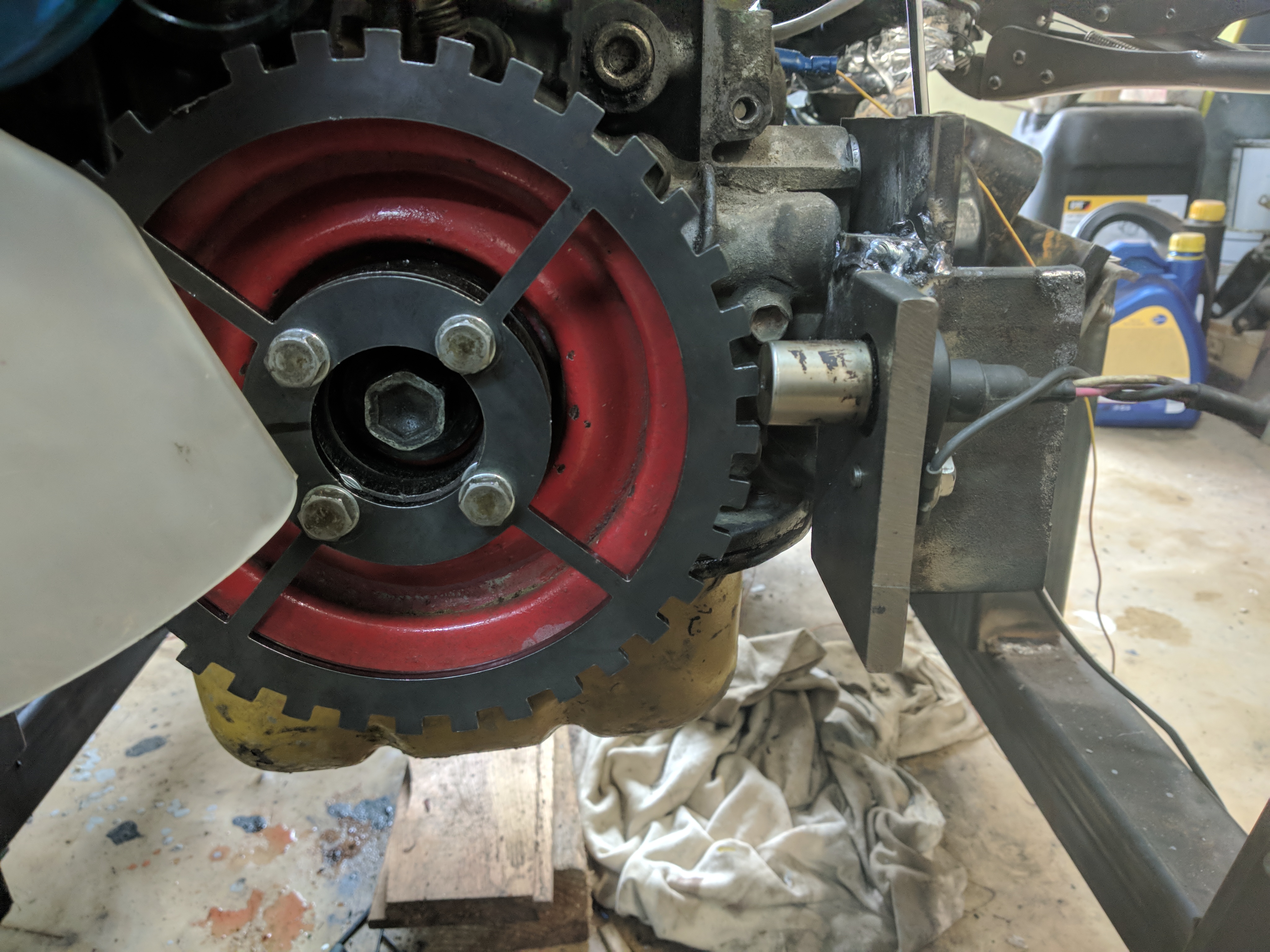
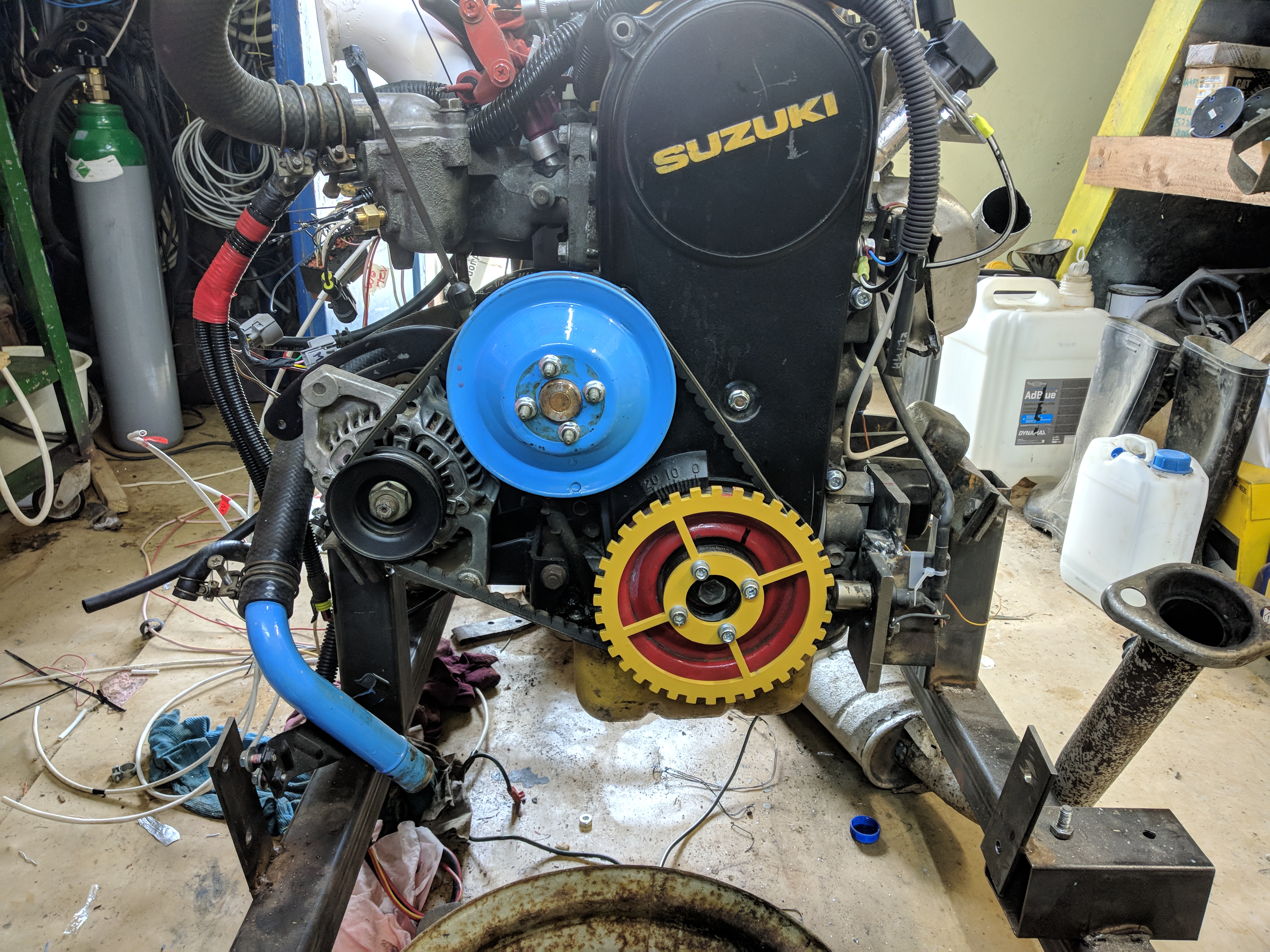
Originally I wanted to only run a 4-1 cam position sensor but I ran into trouble with timing accuracy, I later added a 36-1 crank position trigger wheel and sensor
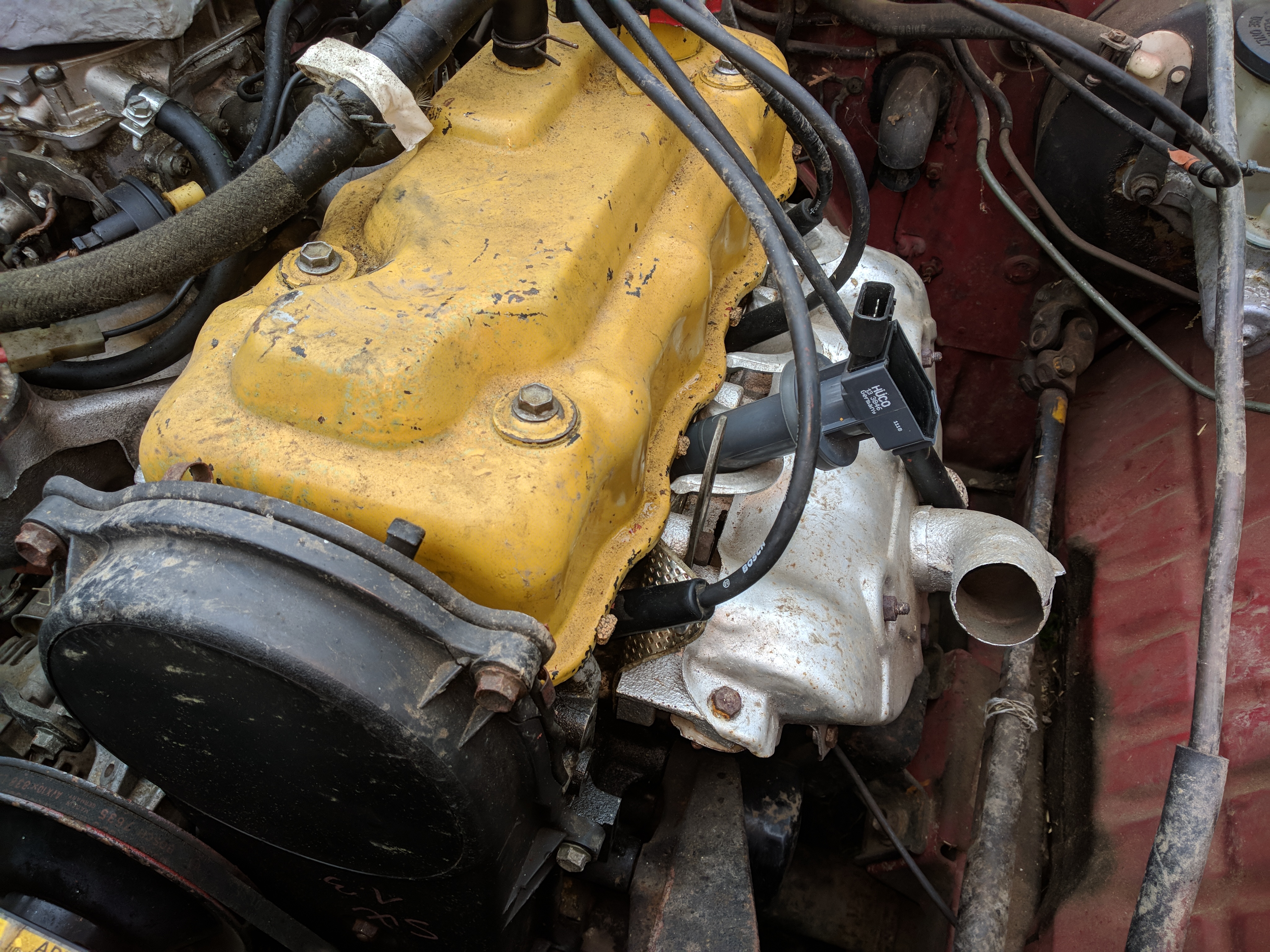
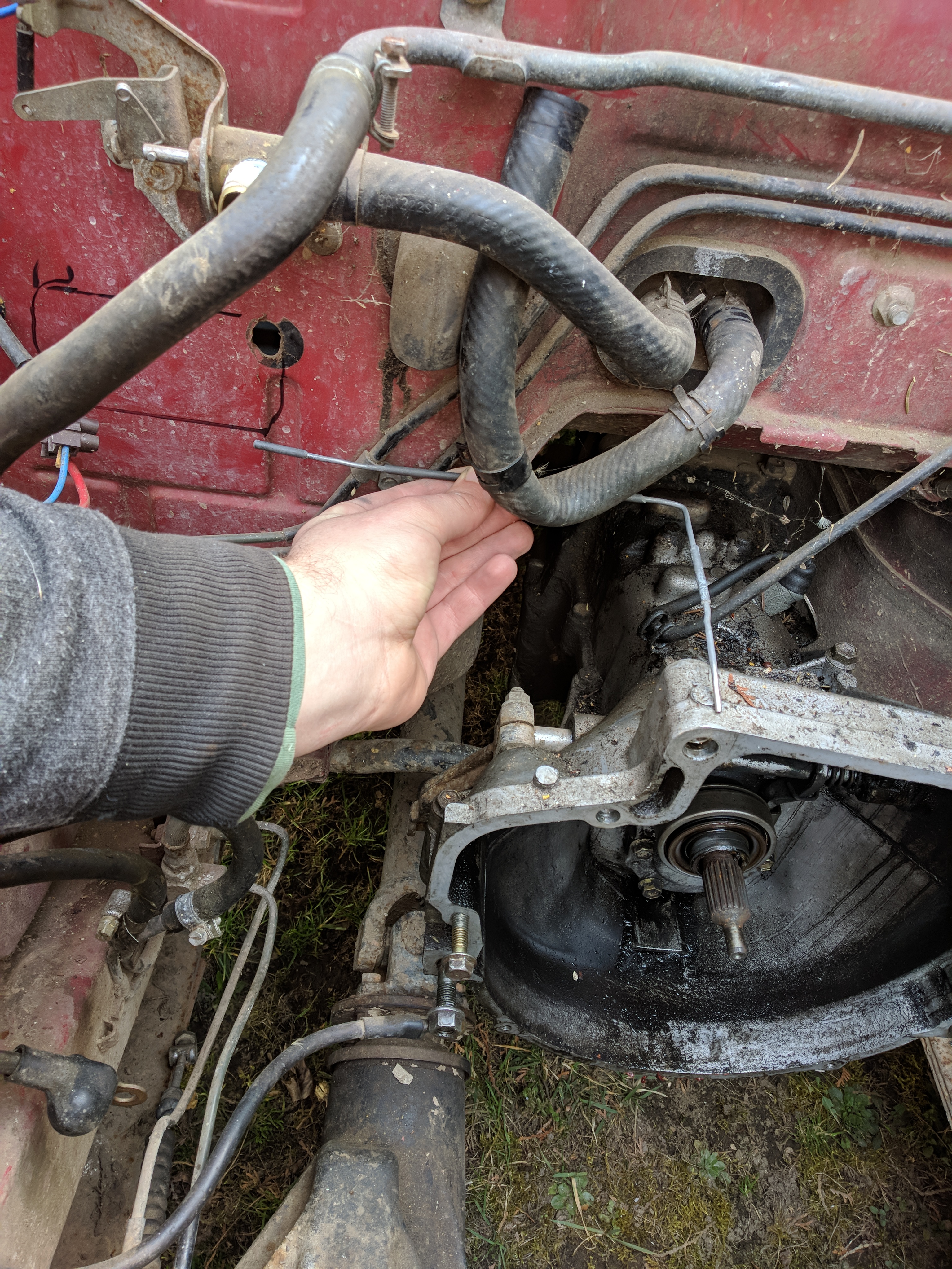
I modified the original contactless ignition distributor by removing mechanical advance, vacuum advance, thyristor igniter, and one of the distributor shaft trigger teeth.
I only need the VR position sensor and trigger teeth.
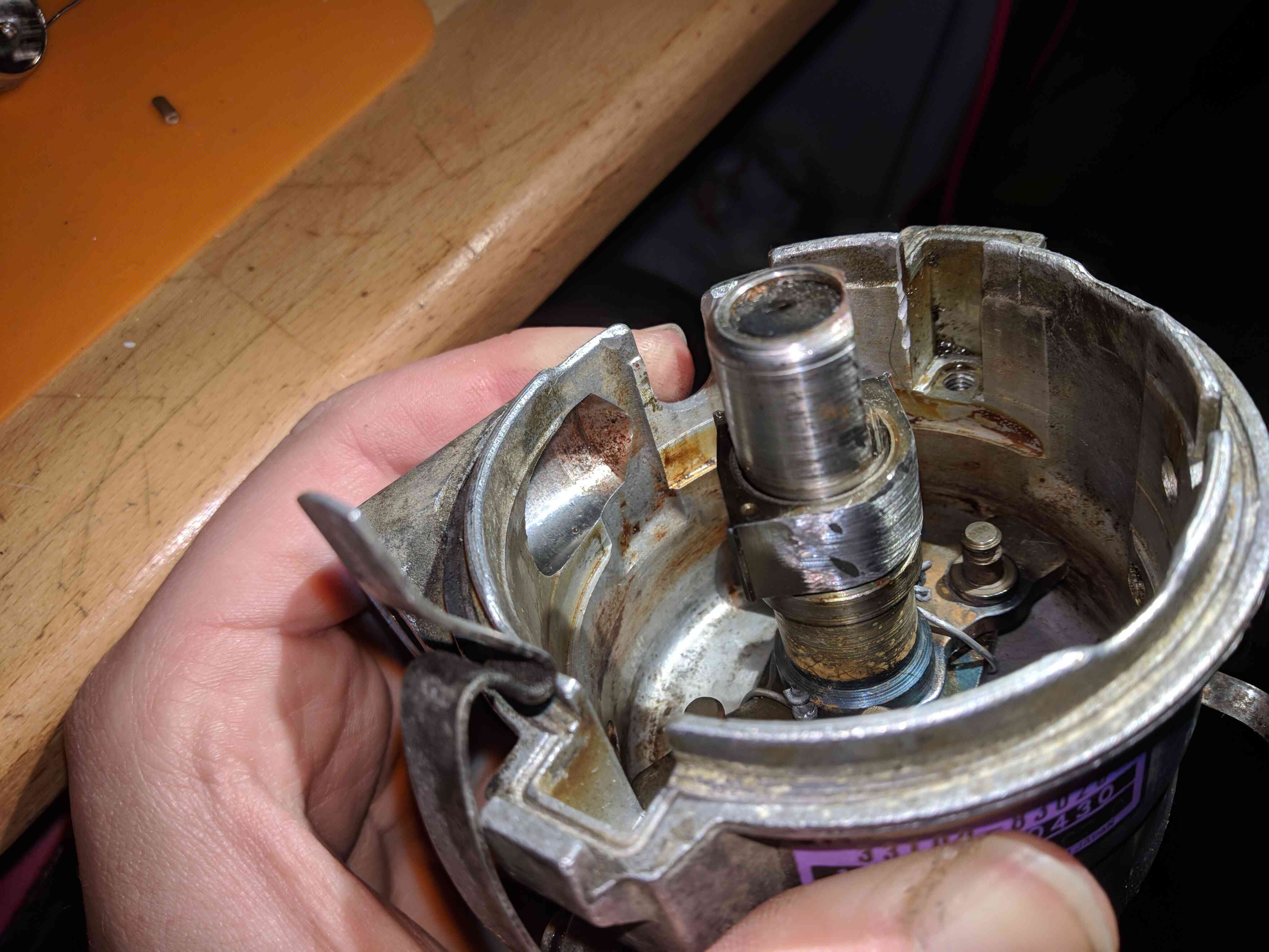
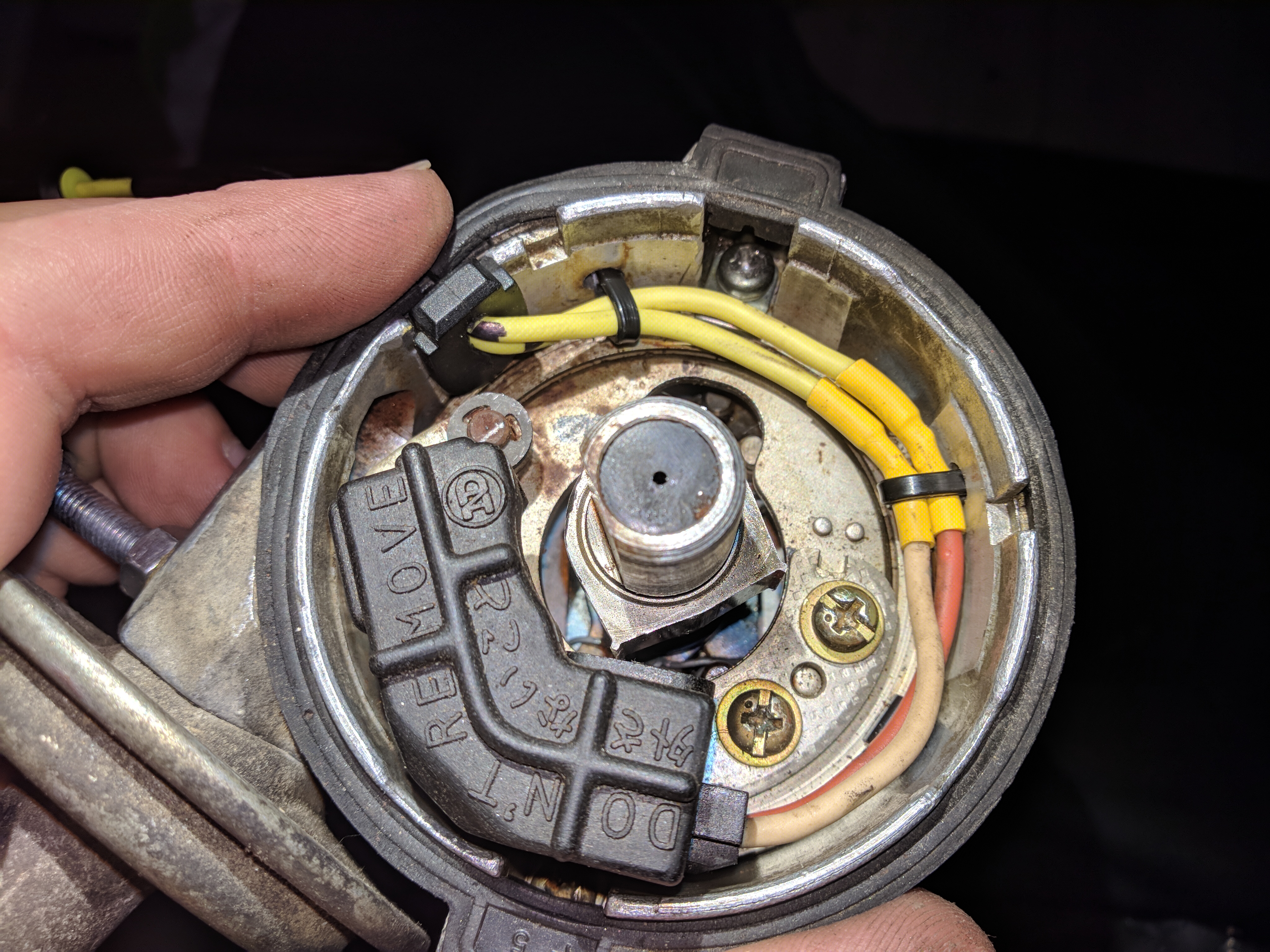
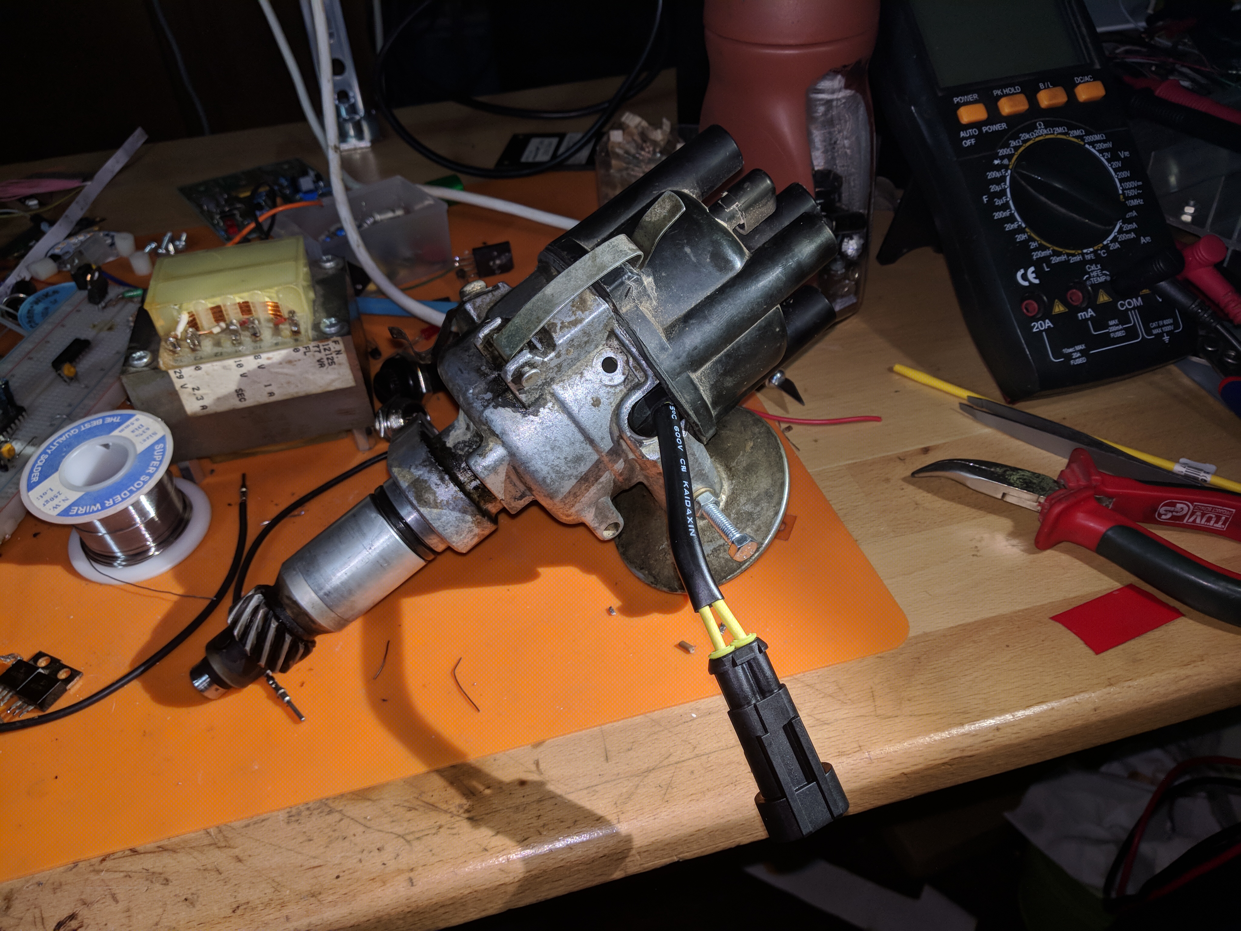
Because of ignition accuracy problems that I ran into with the low resolution trigger, I installed a 36-1 crank position wheel that was plasma cut.
the VR sensor is a Denso DCPS-0116.
Coolant temperature is important for the ECU to know how much extra fuel needs to be added, in cold states the engine needs to run richer than normal. My first plan
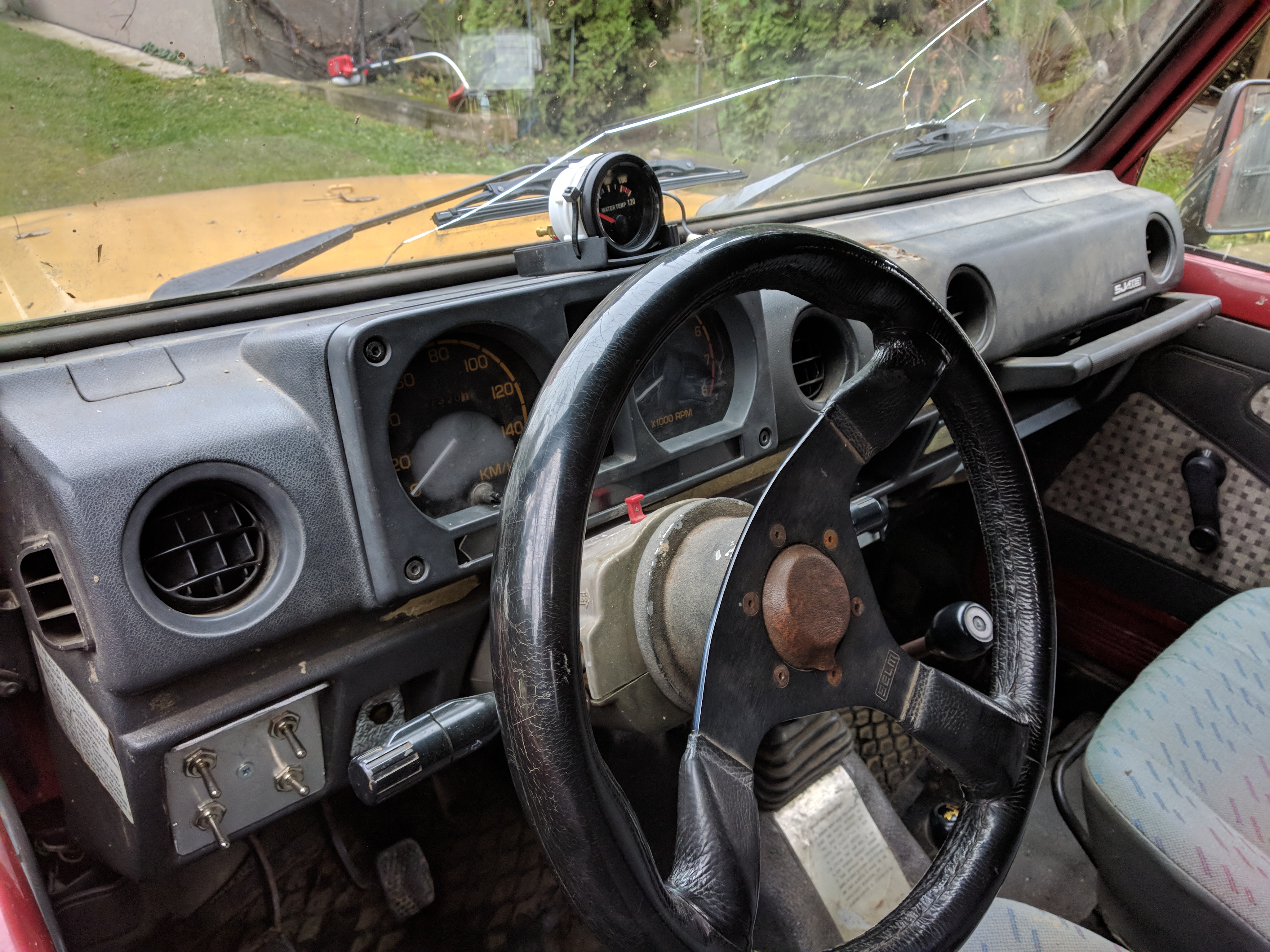
was to use a STK Pt Pt100/B sensor, but it's resistance range is way too low. I switched to an NTC that was a part of a temp gauge kit which was installed after the original gauge cluster's temp gauge failed.
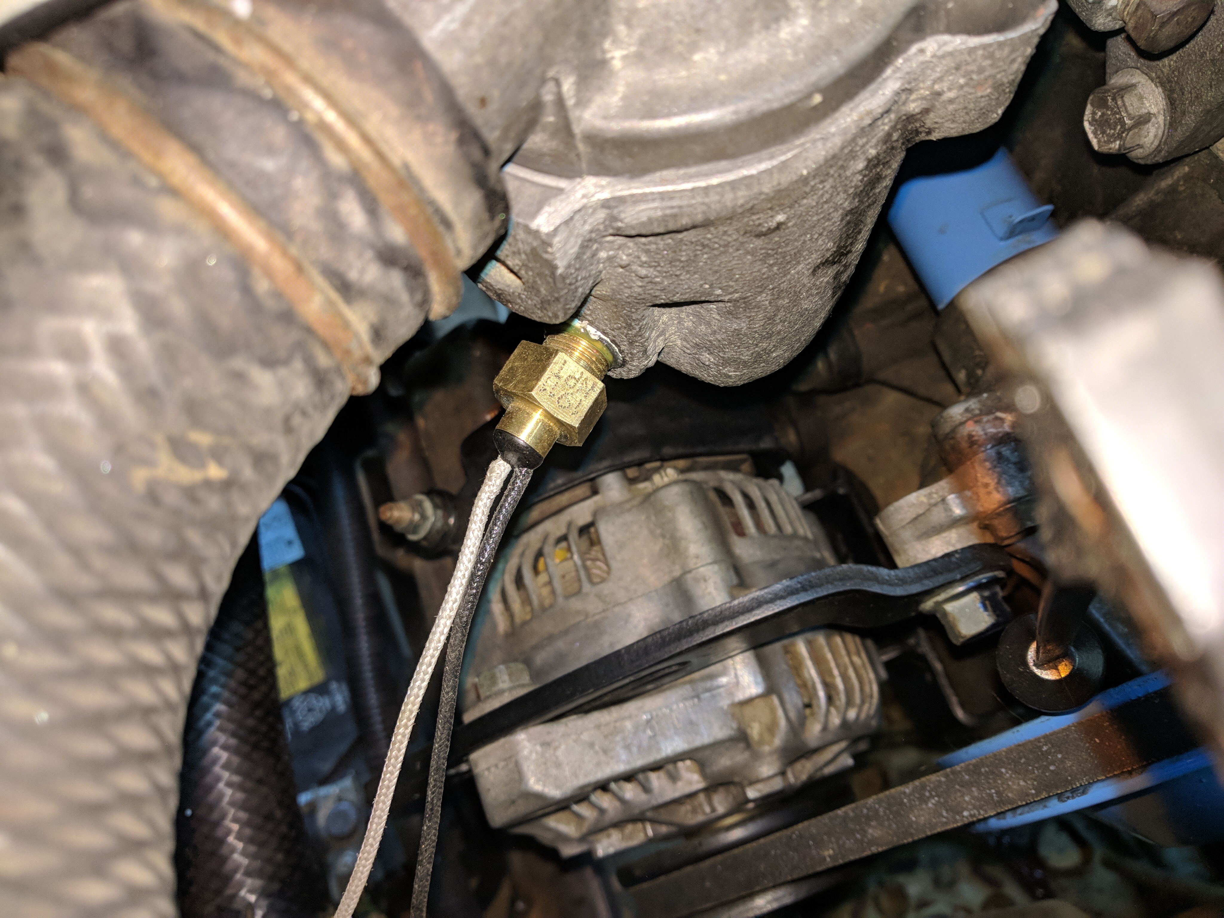
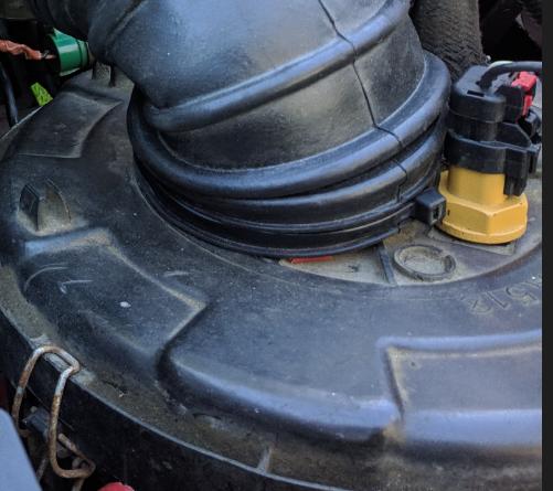
After the PT100 option was deemed not viable i found a CAT 256-6453-03 in my parts box. it is installed directly in the air path on the air box.
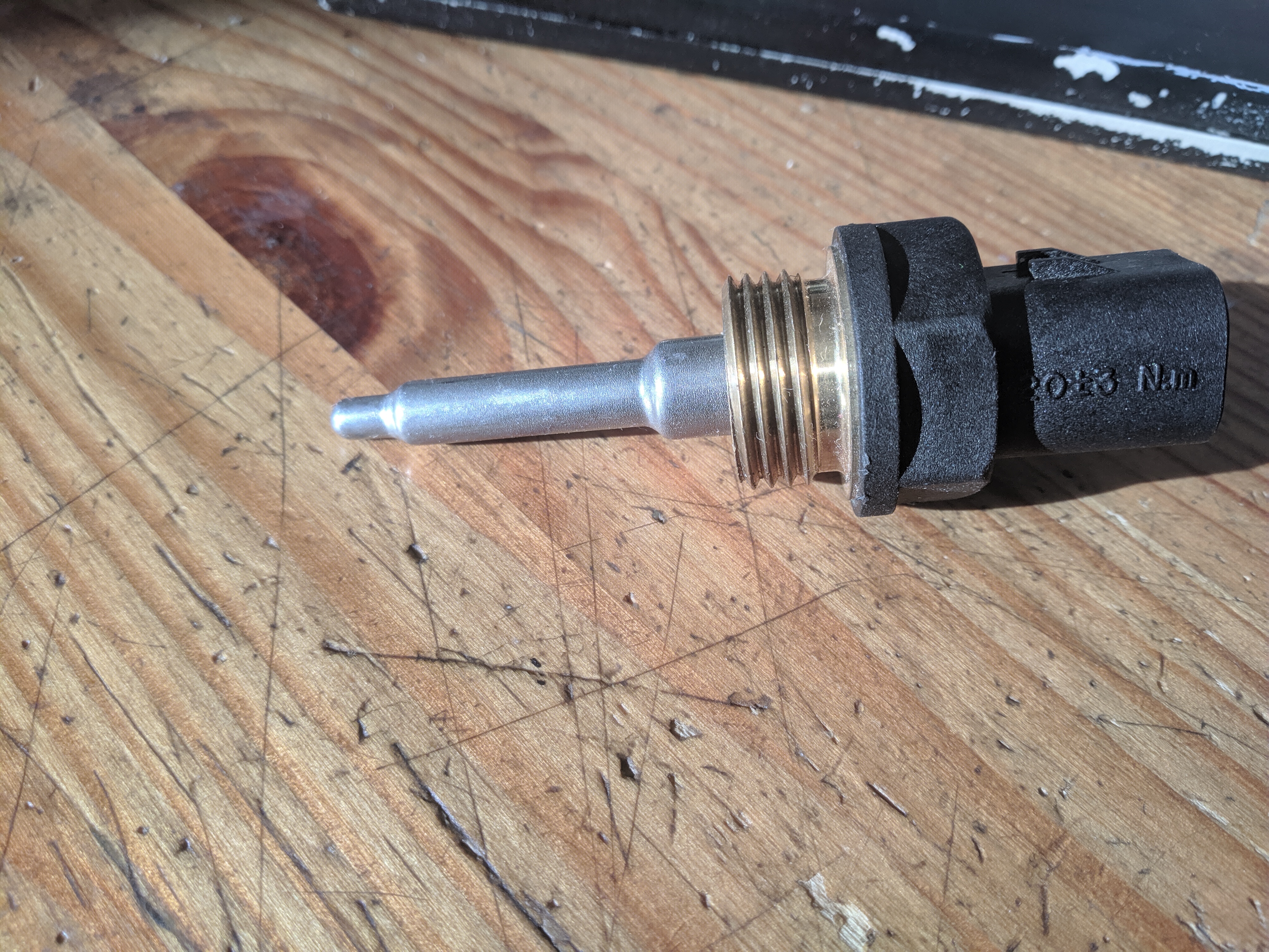
The part instaleld on the car is failing and I also don't have a picture of it. However the solution to both of these problems is the replacement unit that is sitting on my table :D.
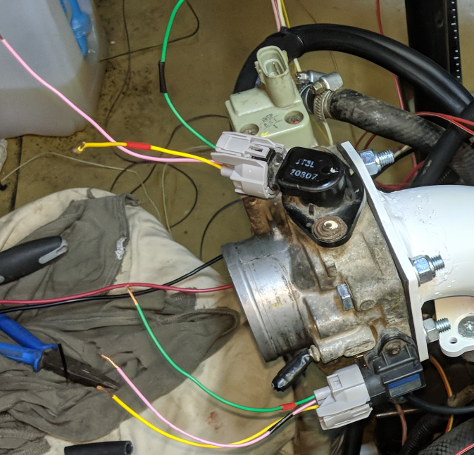
The model used is a Denso 079800-4250, it already came on the throttlebody and has a 0-5V output.
Integrated potentiometer on the throttlebody, not much to it.
Originally belongs to a Honda D14, I chose this part because of it's integrated MAP sensor, TPS sensor, and IACV. It's meant for around 60-90kW but it is way too big,
this variant of the G13 makes around 55kW peak power. This throttlebody is good for high load but it sacrificies greatly in granularity, I don't even open it fully.
Rapid movements around 1700RPM(crawling speeds) it causes a spike. I'm still considering getting a smaller throttlebody.
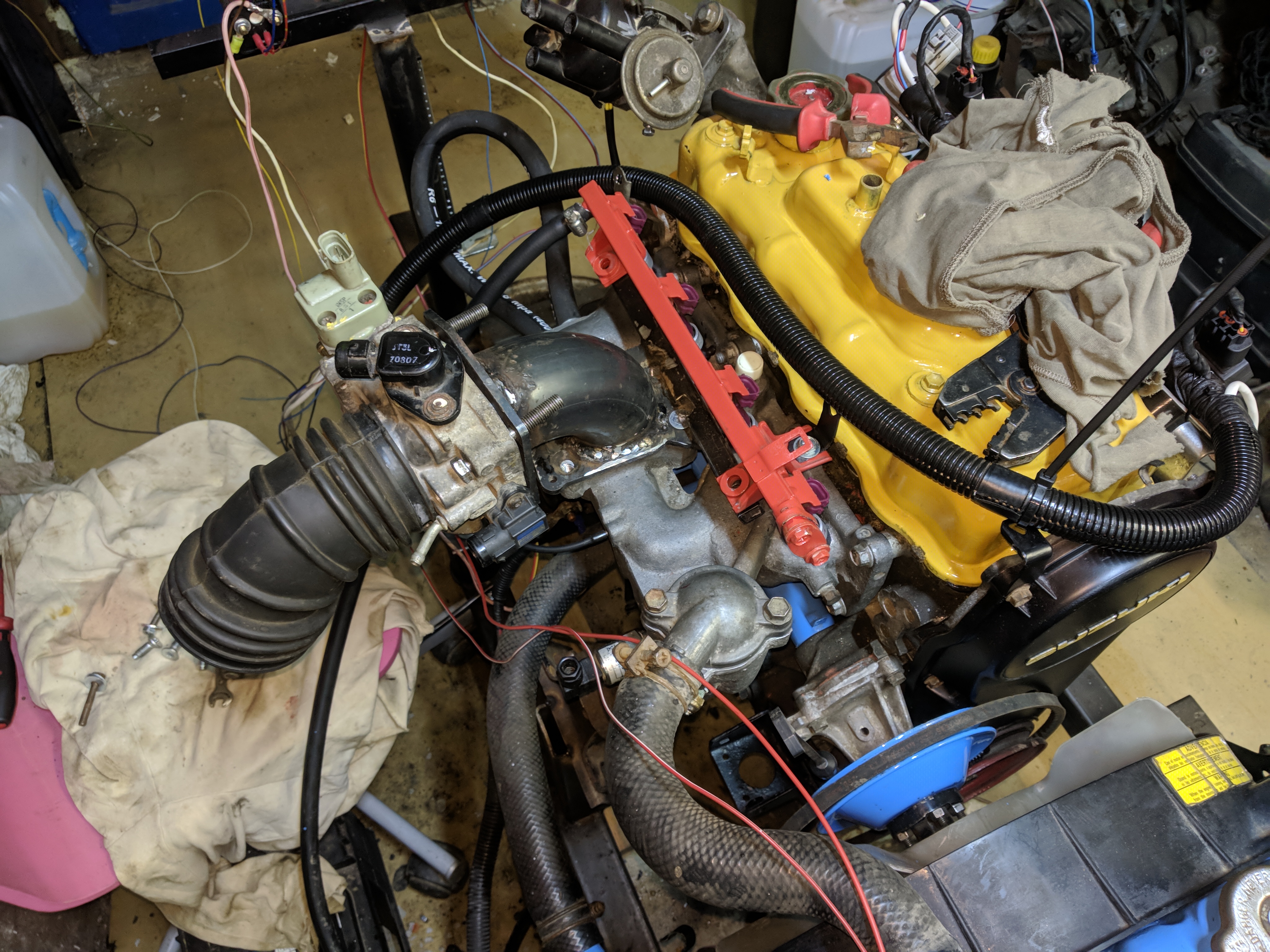
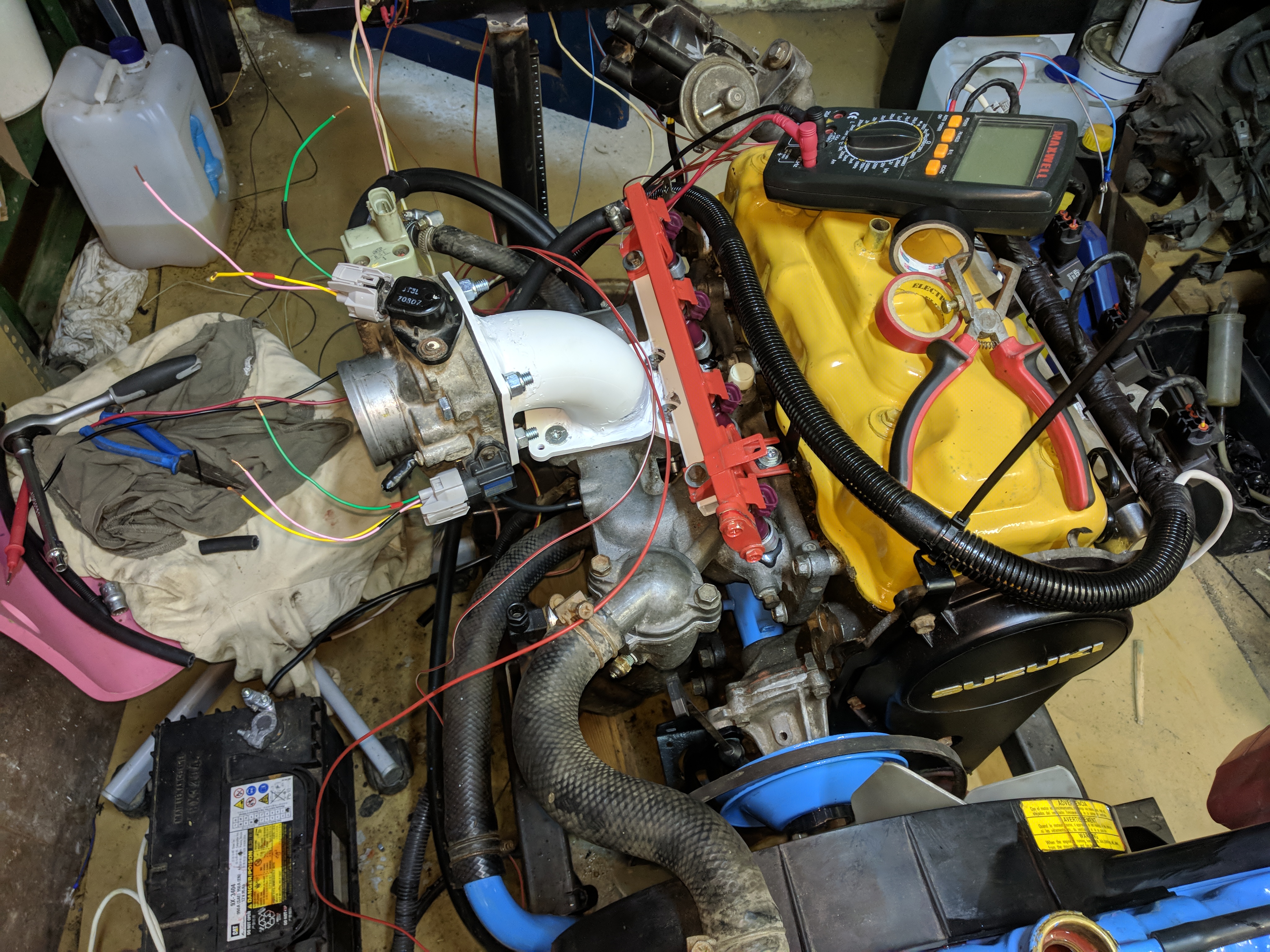
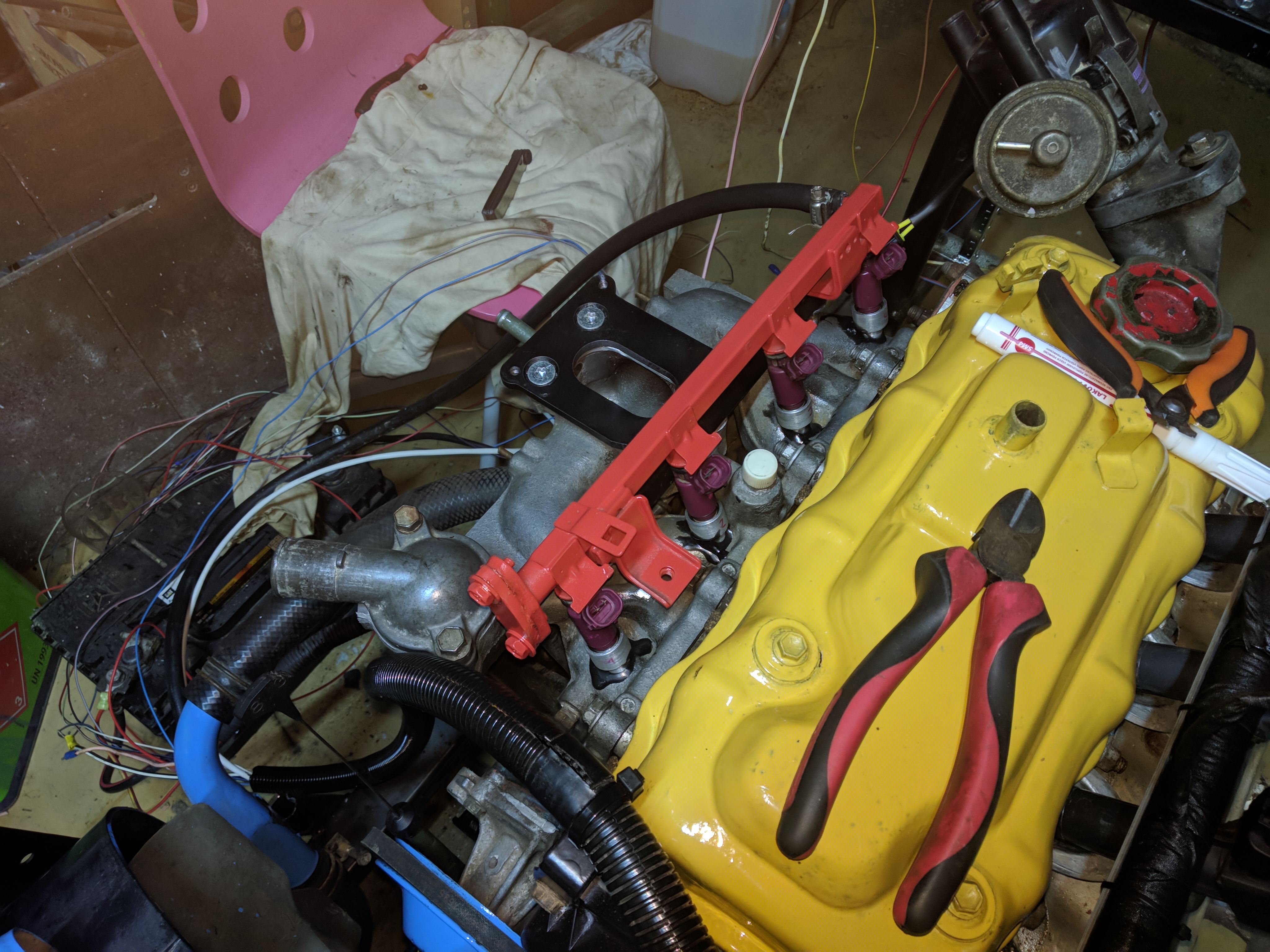
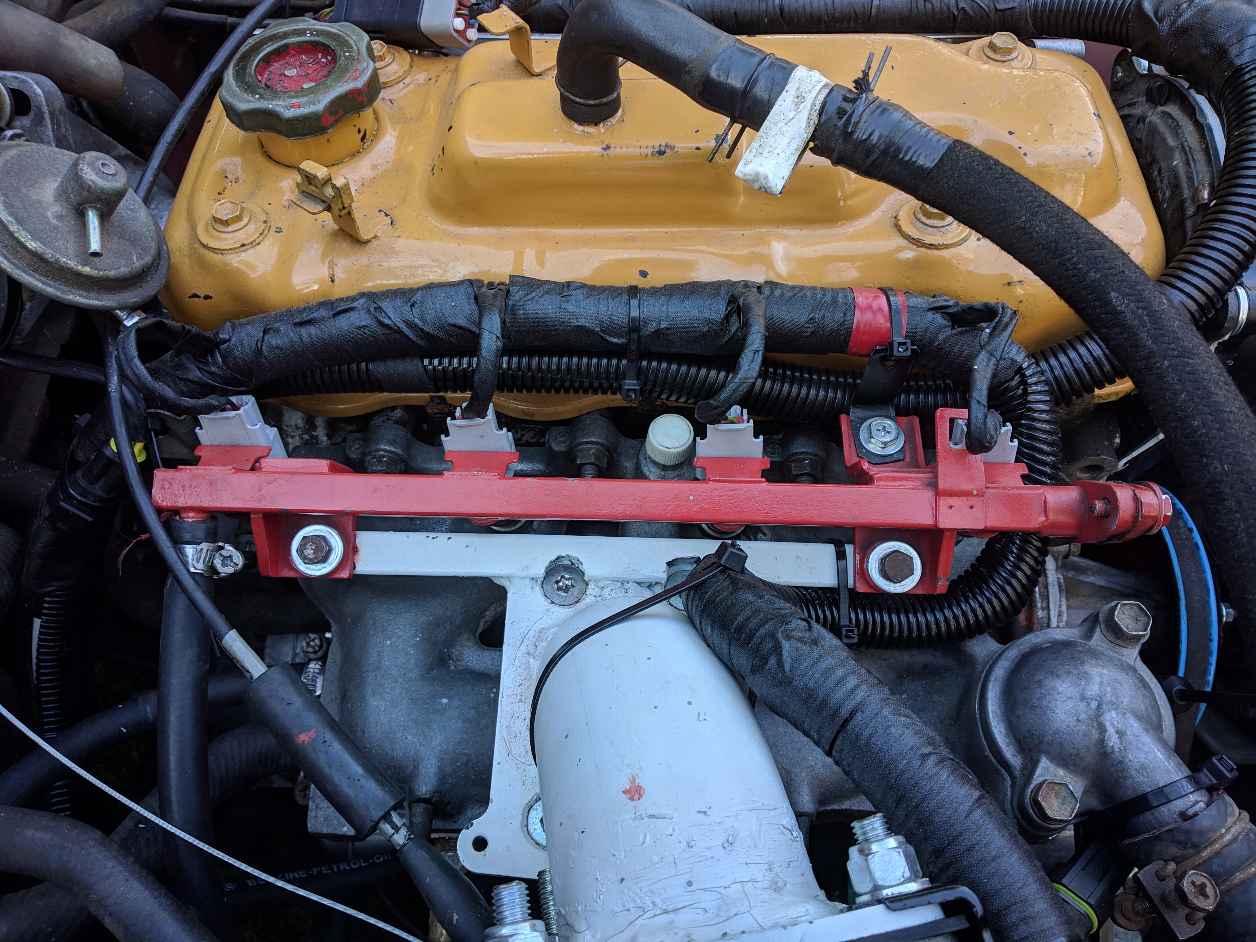
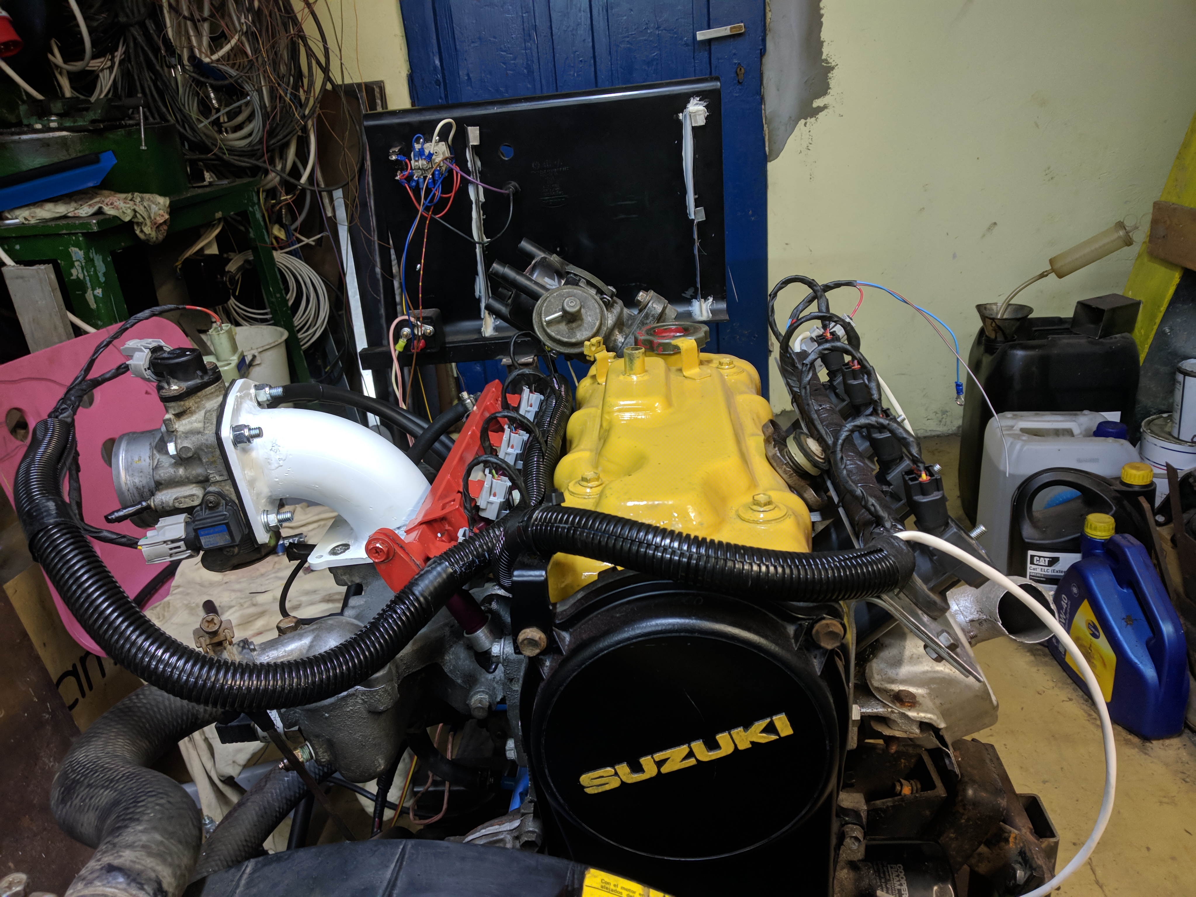
The throttlebody is mounted to an elbow coming off the intake, intake flange is an adapter for the 2e3 carb. This structure also holds the fuel rail. It was welded by my father because my TIG welding was quite poor at the time.
With this position the originally intake hose and airbox are fully compatible.
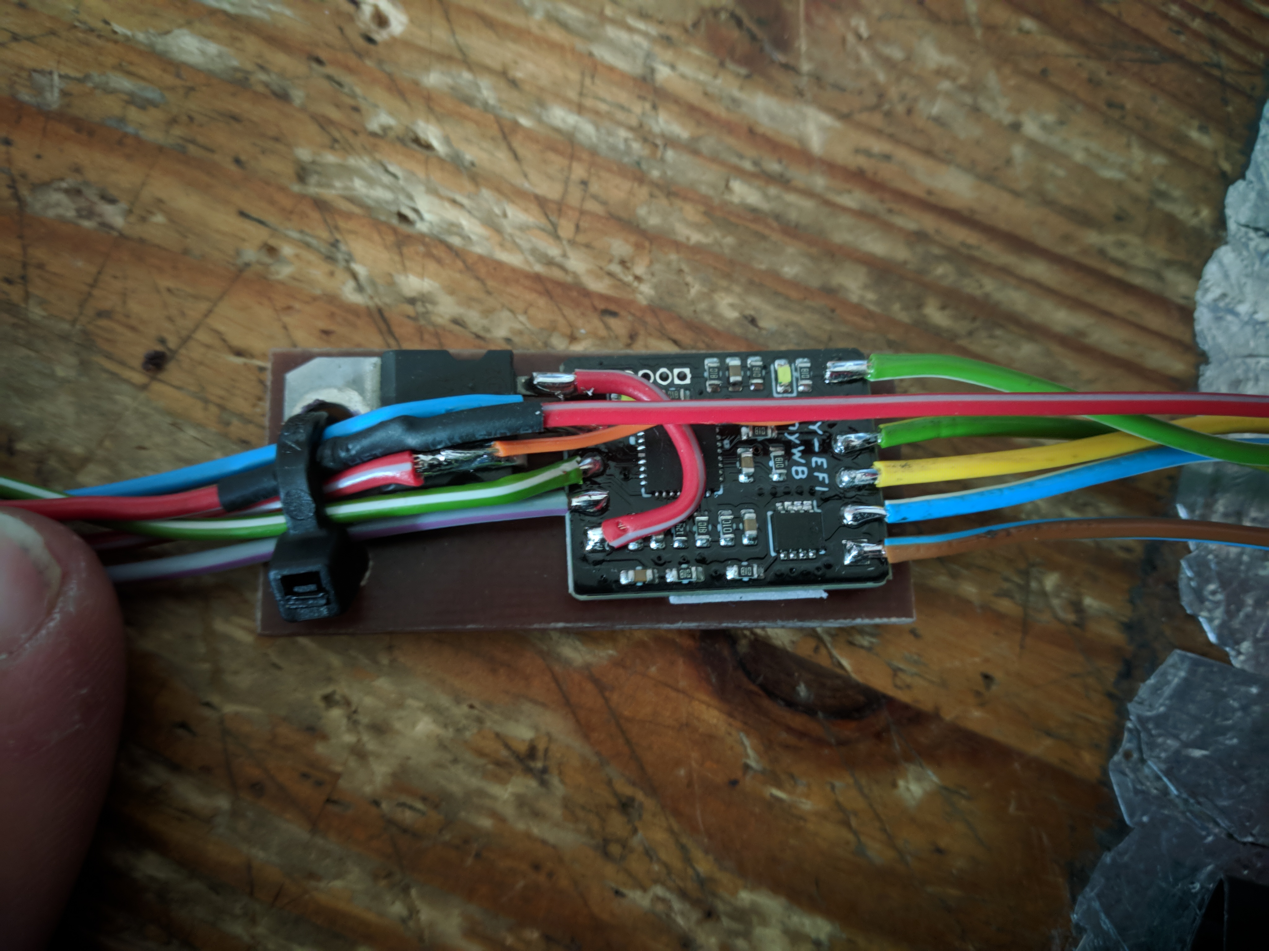
I used a BOSCH LSU4.9 sensor which is quite popular and proven. Widebands like this need a driver to convert their raw signal into a linear analog voltage.
It is recommended to only power the heater shortly after the engine is started, after the condesation is gone, but not so far after that carbon has a chance to build up.
Programable outputs make this very easy.
As mentioned above, LSU4.9 needs a controller. I used a DIY-EFI TinyWB because of it's small size, ease of use, and cost.
I was planning to run 5V to it but it ended up being easier to have a regulator right next to it from swtiched 12V.
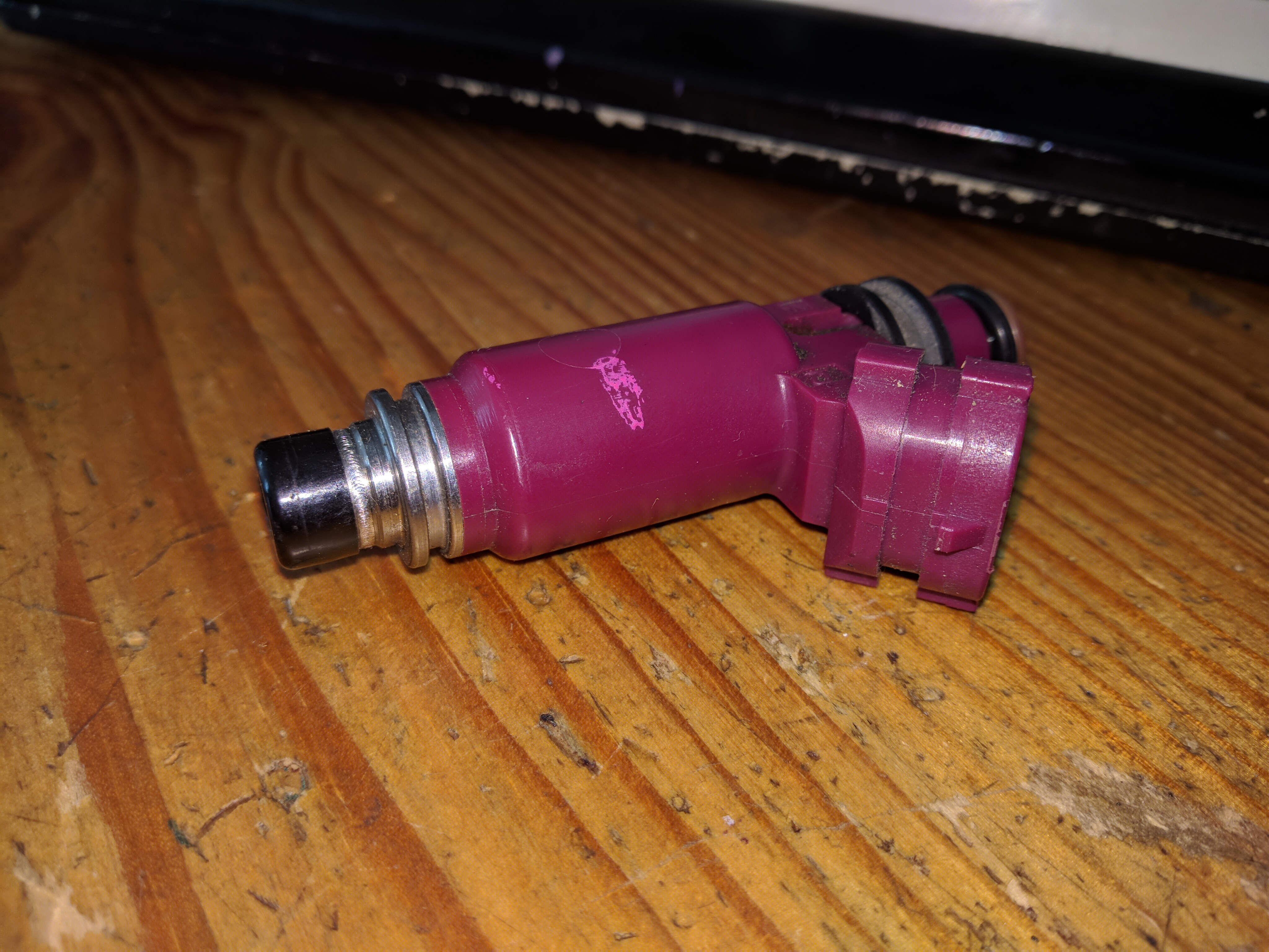
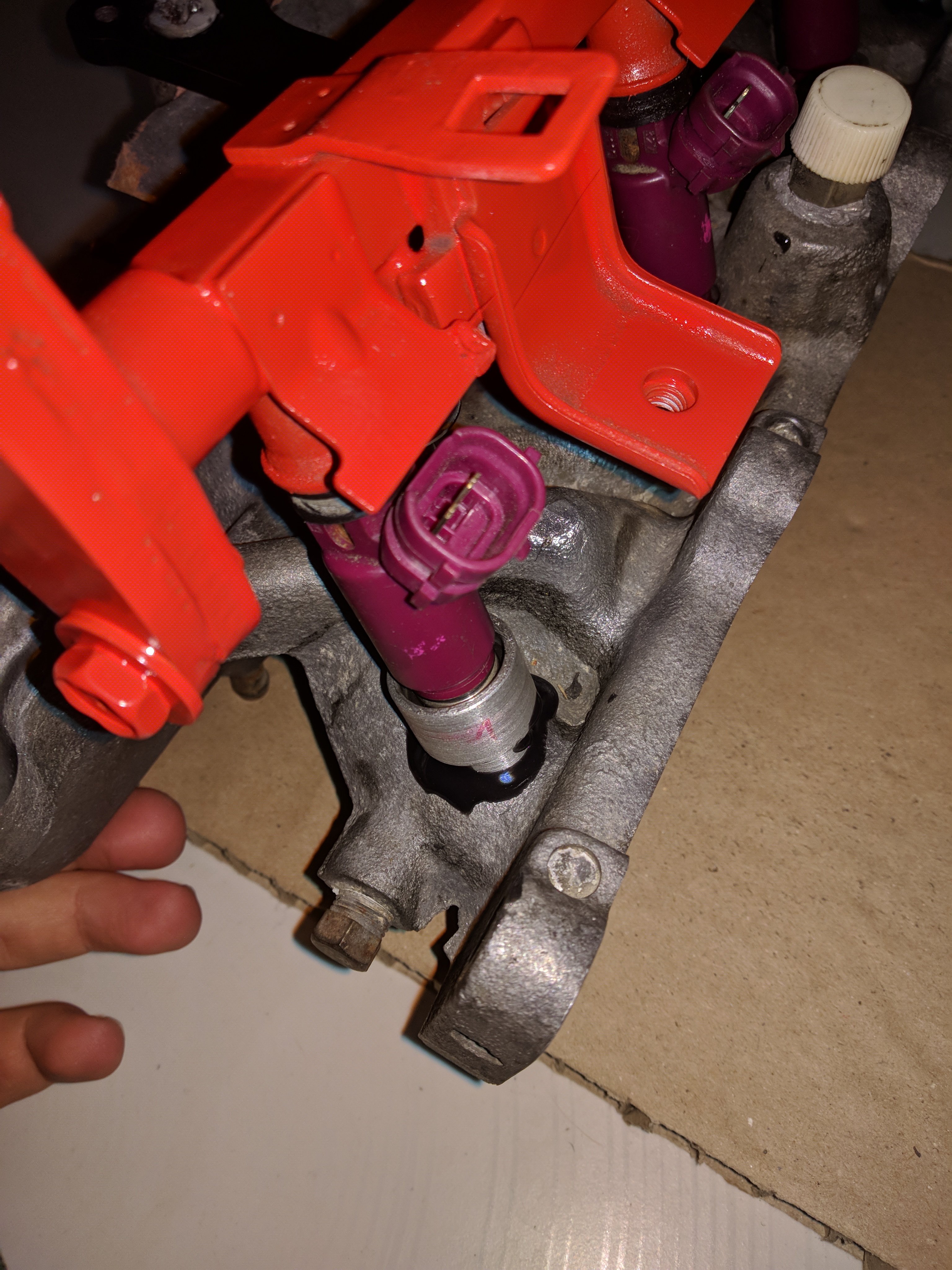
I purchased the injectors and the fuel rail as a bundle, I picked them based on flow rate and distance between each injector. They are DENSO 23250-97401 and the fuel rail belongs
to a Daihatsu HC-E. The flow rate is 240cc/min, roughly capable of up to 110kW. It's an EV14 48mm style injector without any dedicated mounts, it is standwiched in place on the seals.
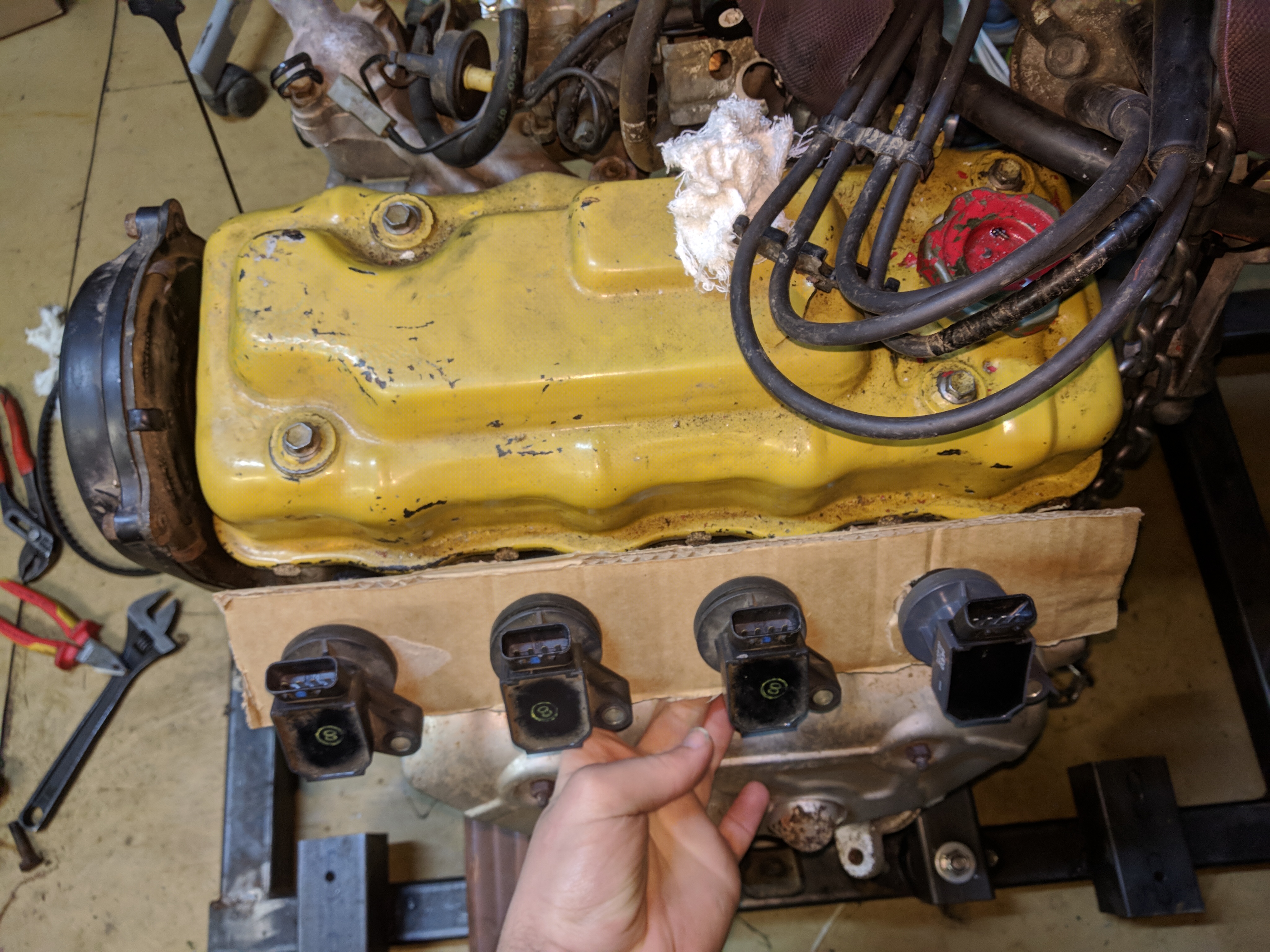
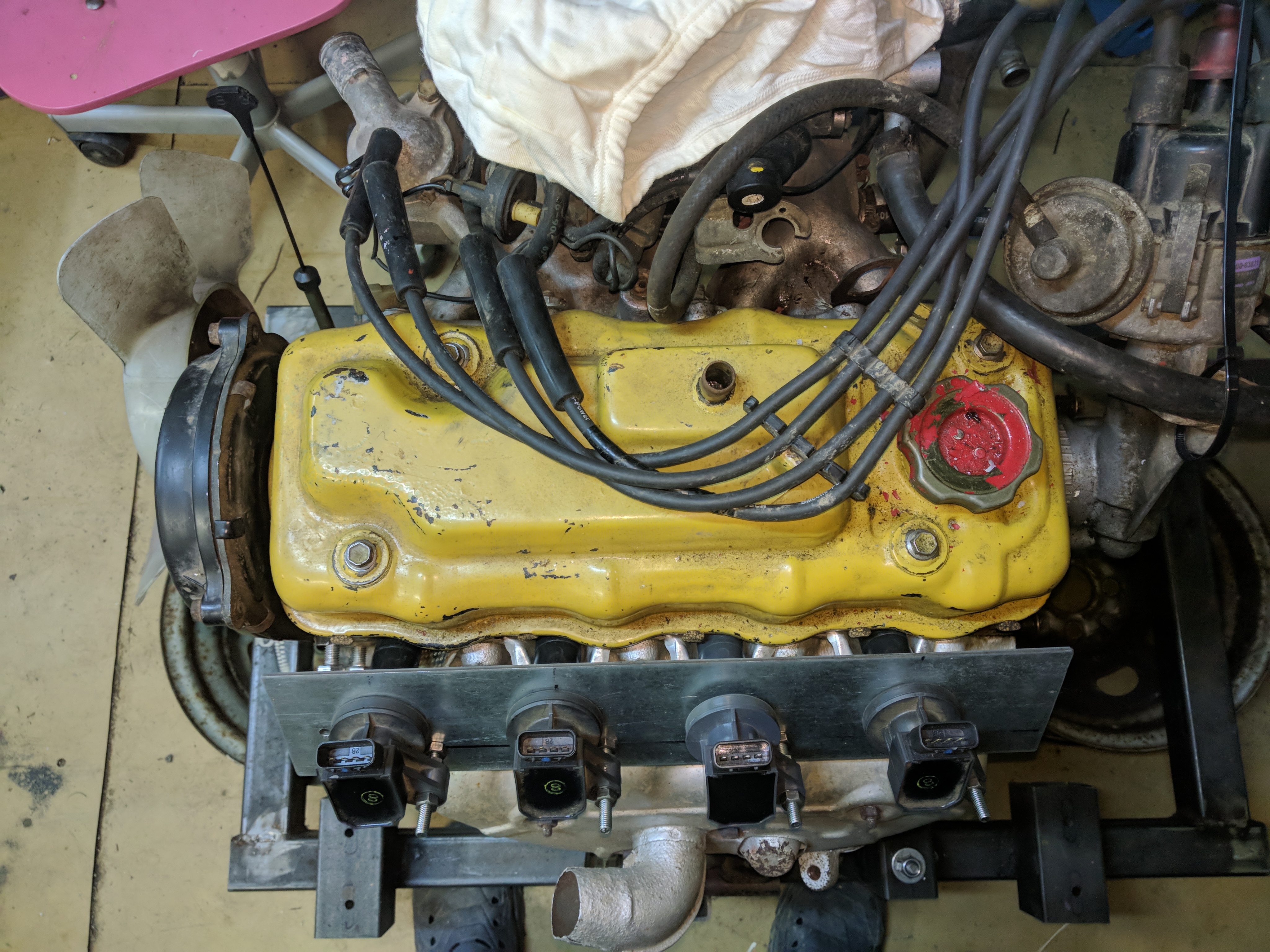
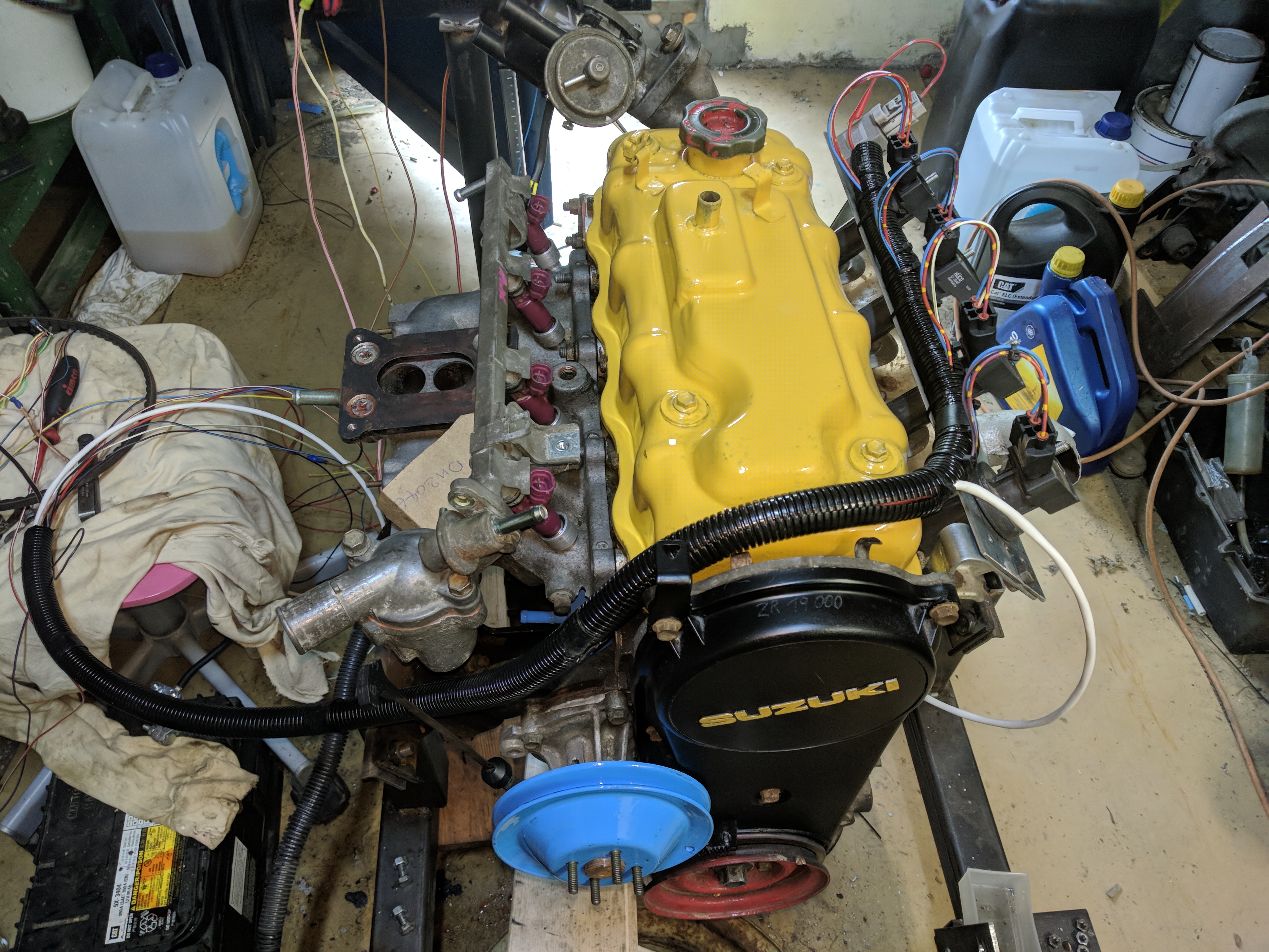
The engine came with a single coil and a distributor. The simplest upgrade would be a two channel wasted spark module VW 032905106B,
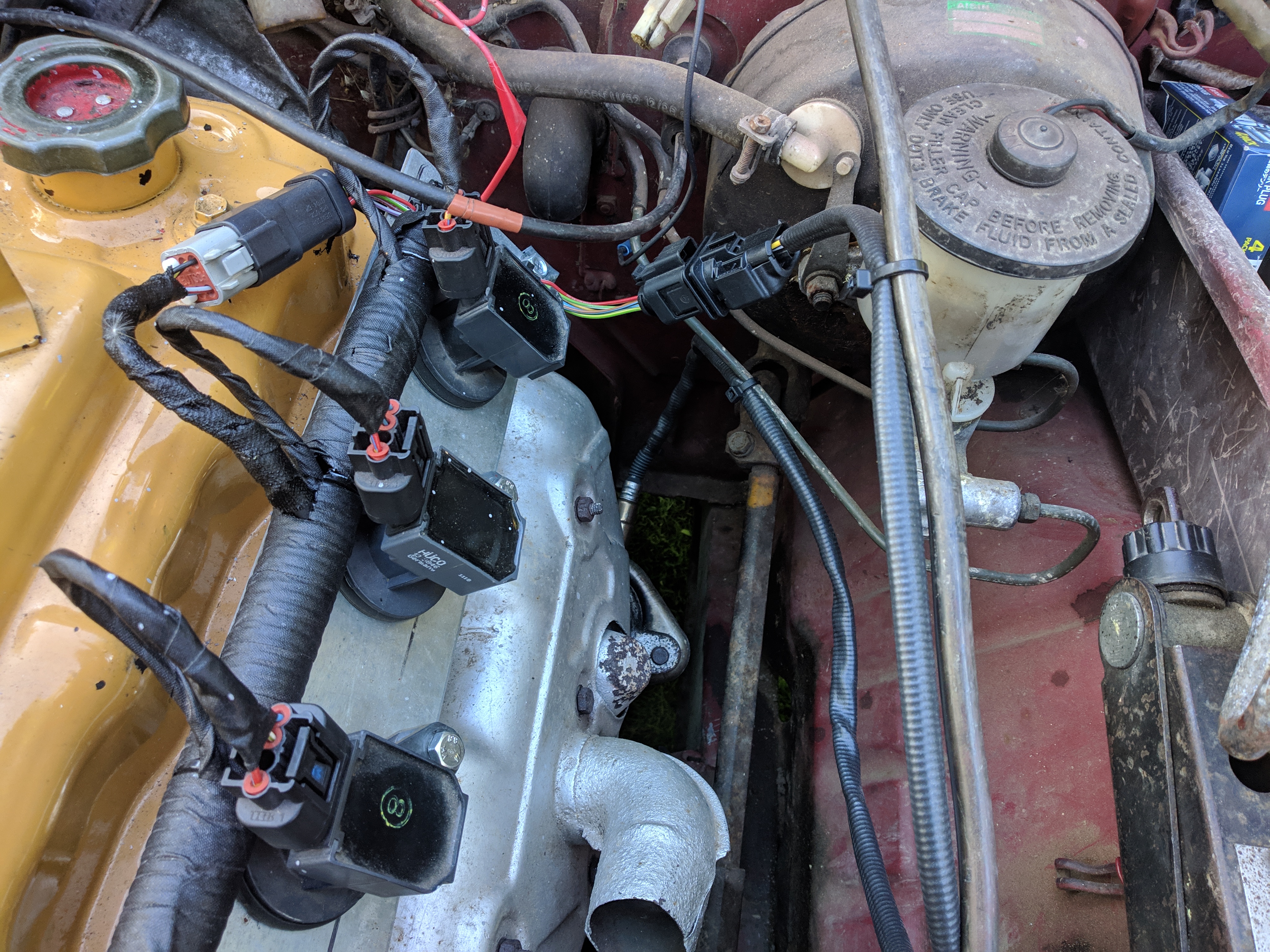
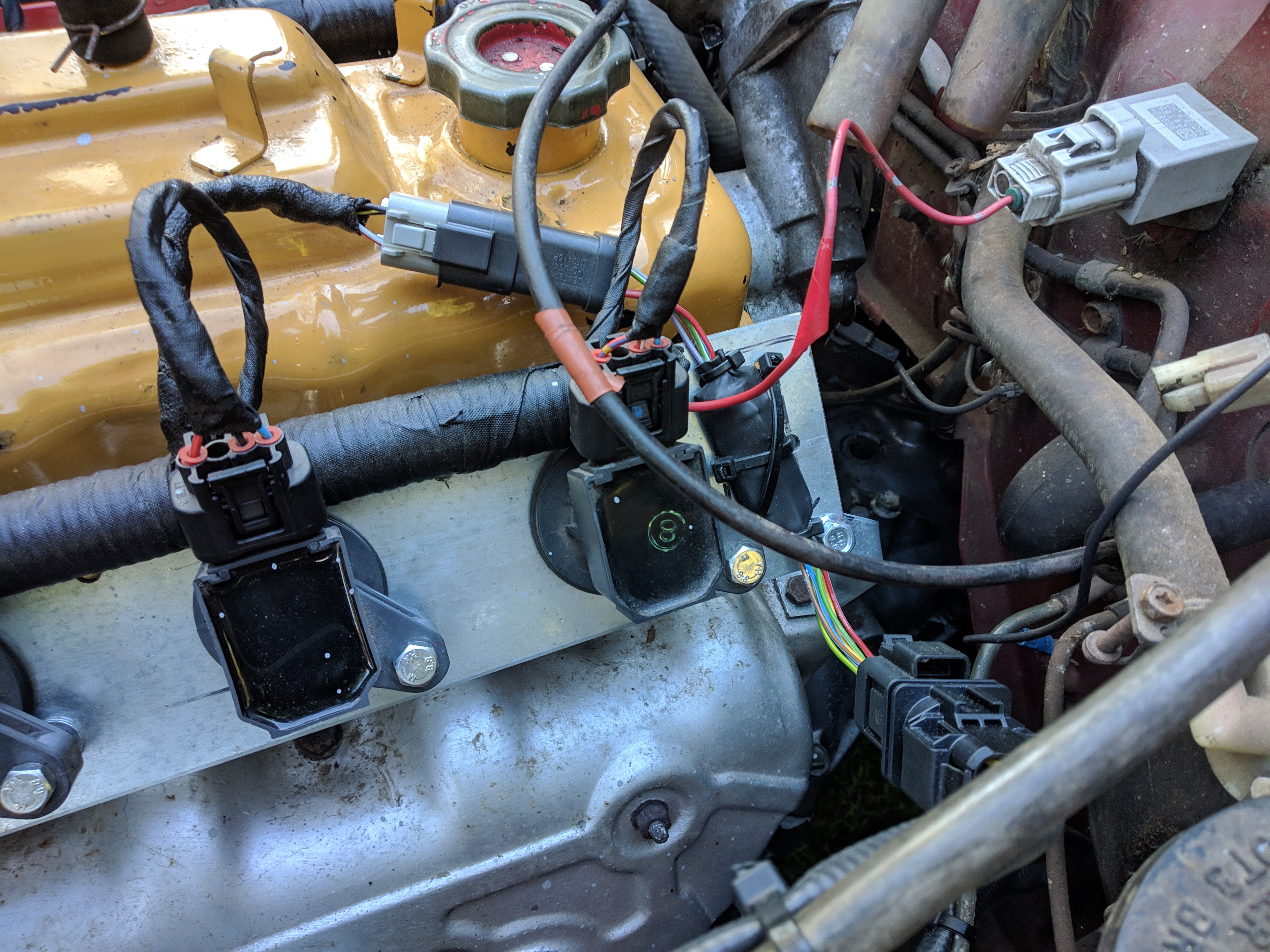
this module would also be compatible with the original plug wires and NGK W0133-1641758 spark plugs. However my goal is fully sequential operation, so I chose individual DENSO 90919-02239 smart coils.
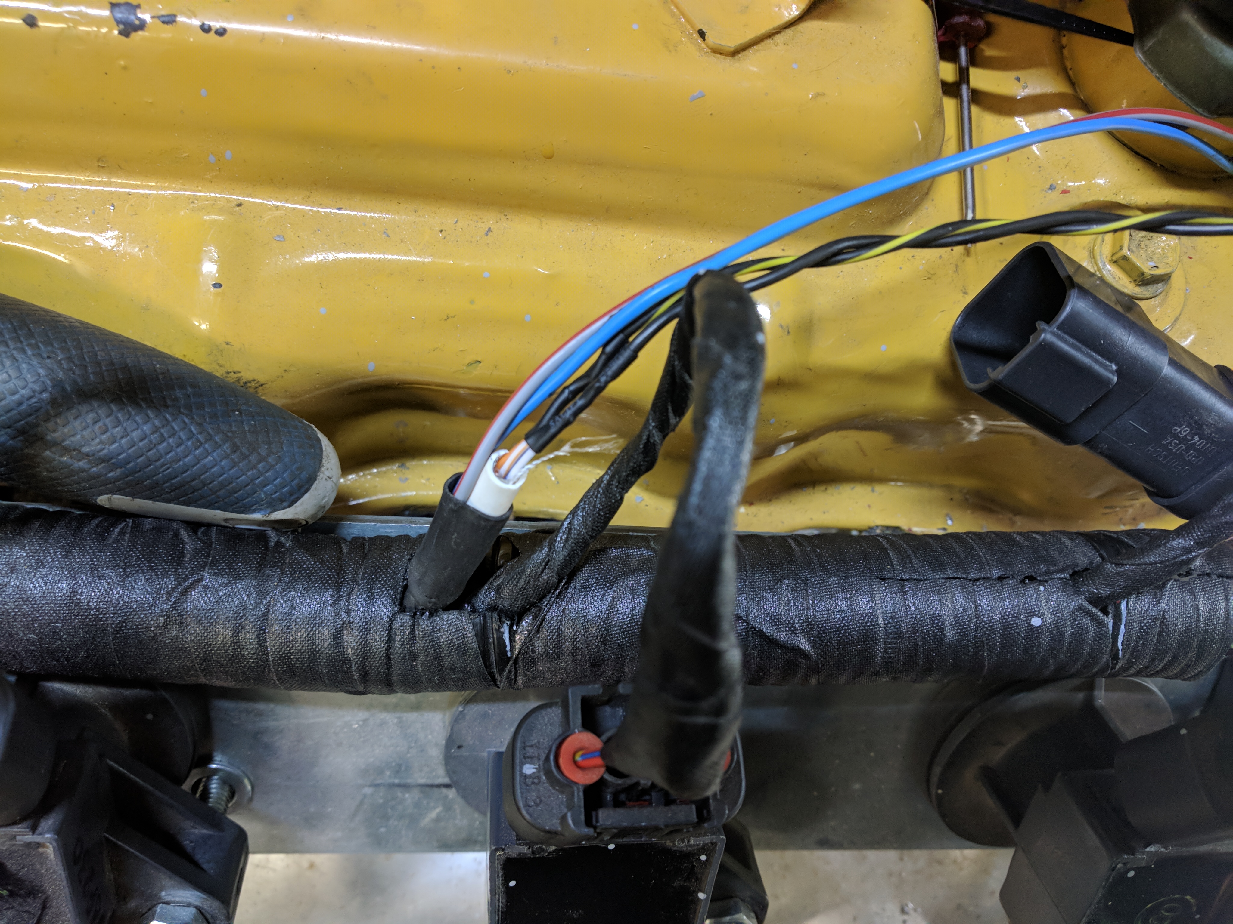
These individual Coil On Plug coils have a far stronger spark and one of the advantages is far better ignition of the fuel. One of the side effects is that the stock spark plugs can't handle this,
which is why I replaced them for DENSO K16R-U11. COP coils are meant to be deep inside the cylinder head, this shields them from the rest of the electronics. Here not so much.
During testing i ran into severe EMI problems, i fixed this by shielding the boot of the coil with aluminium tape and grounding it to the zinc plated bracket.
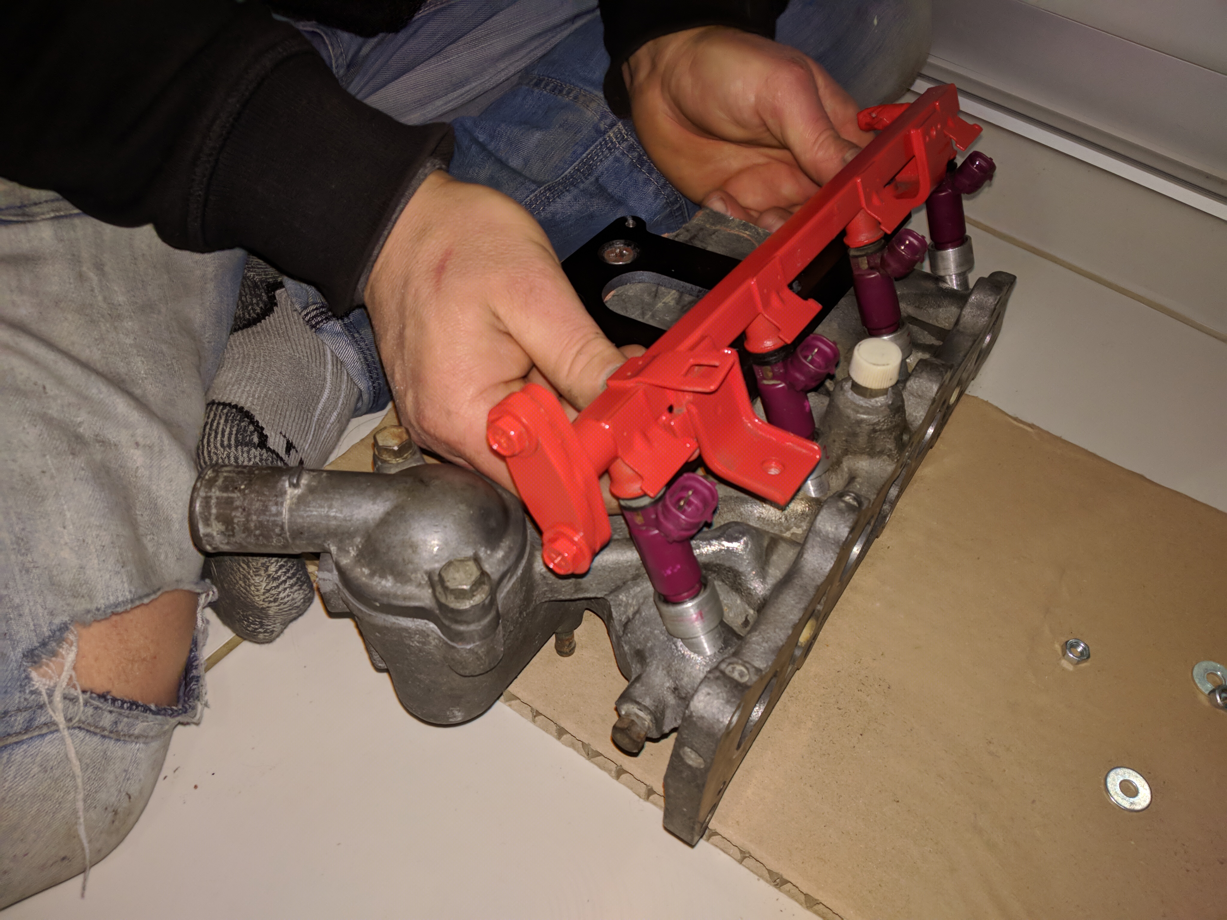
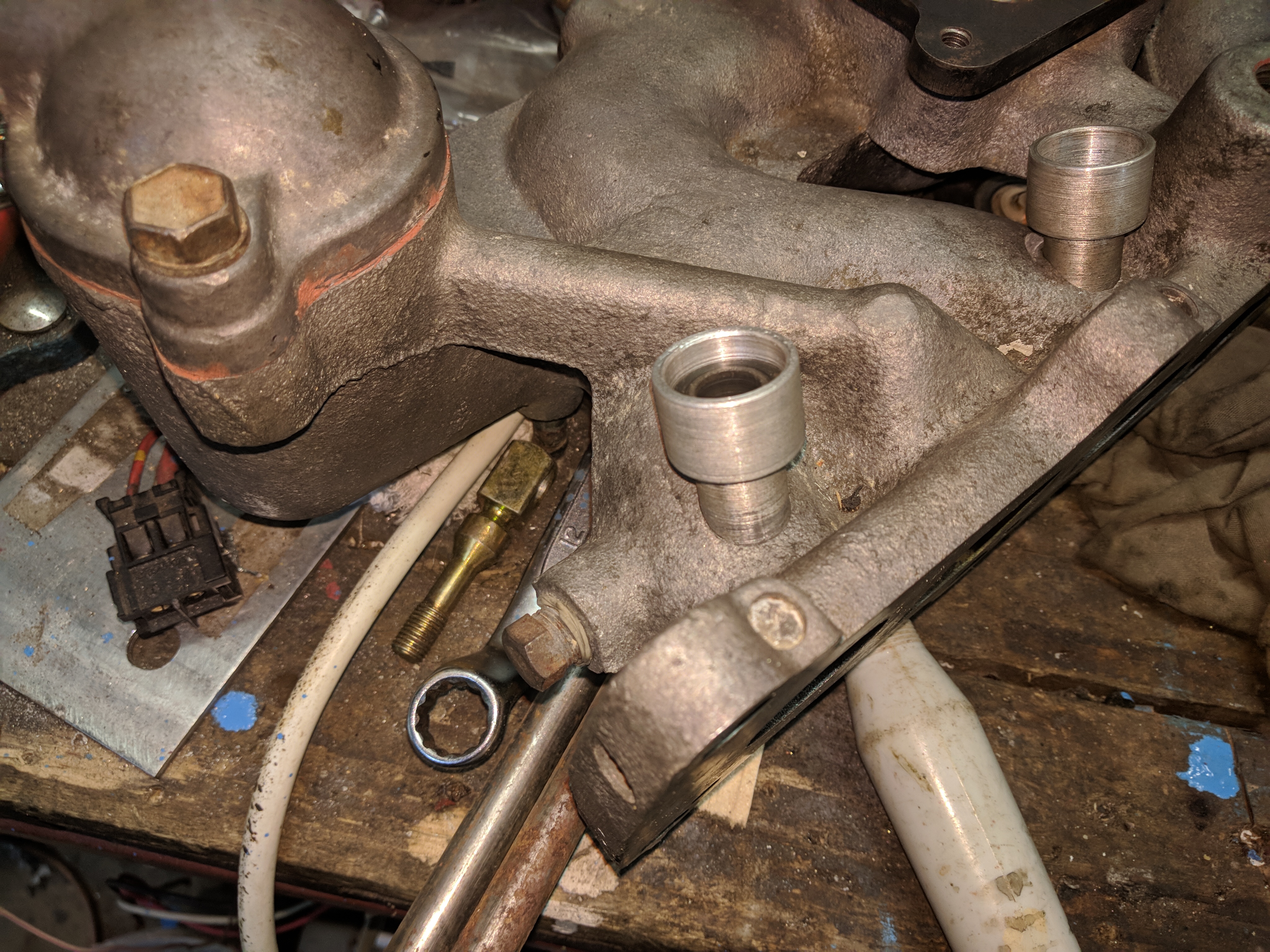
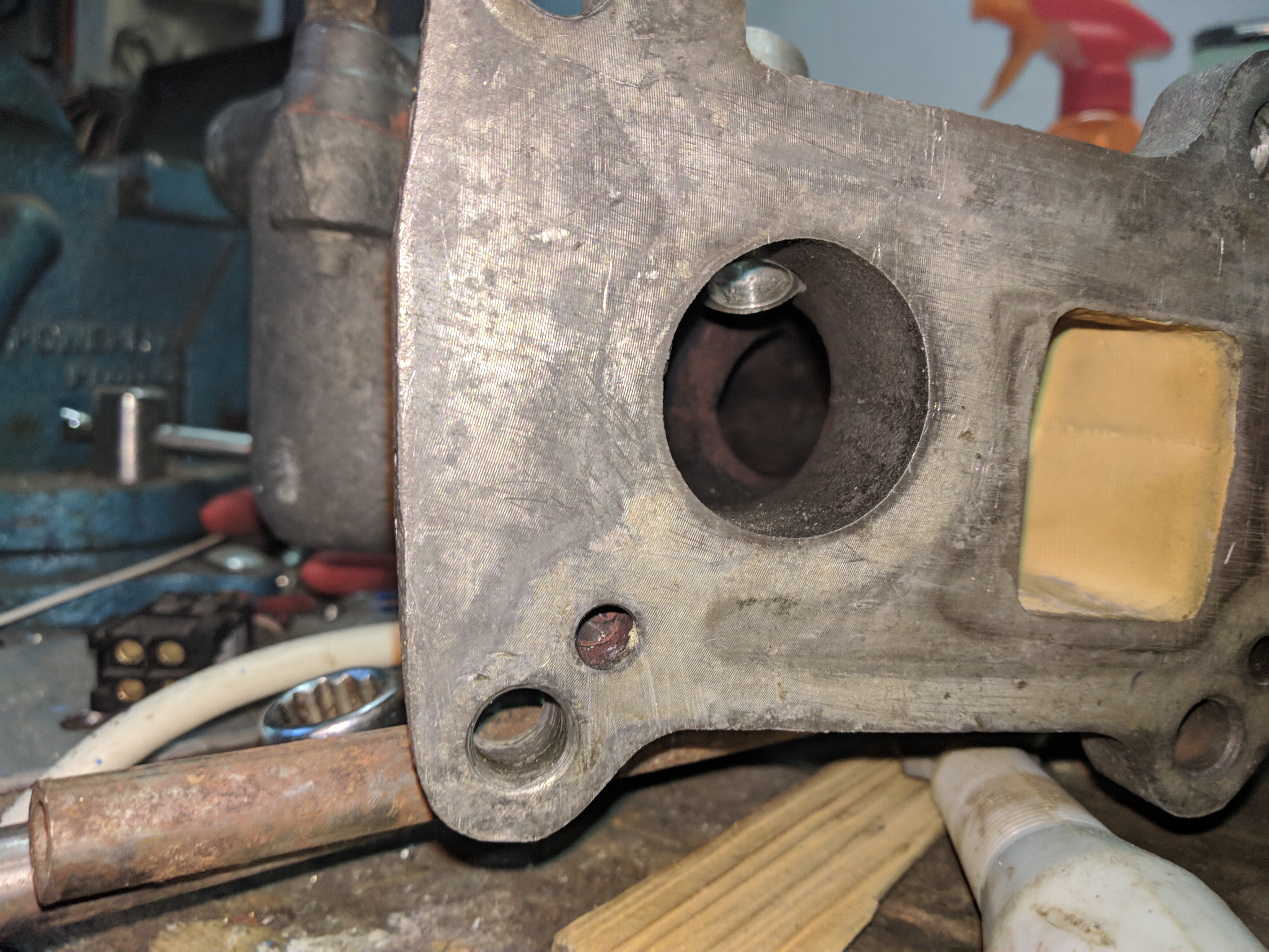
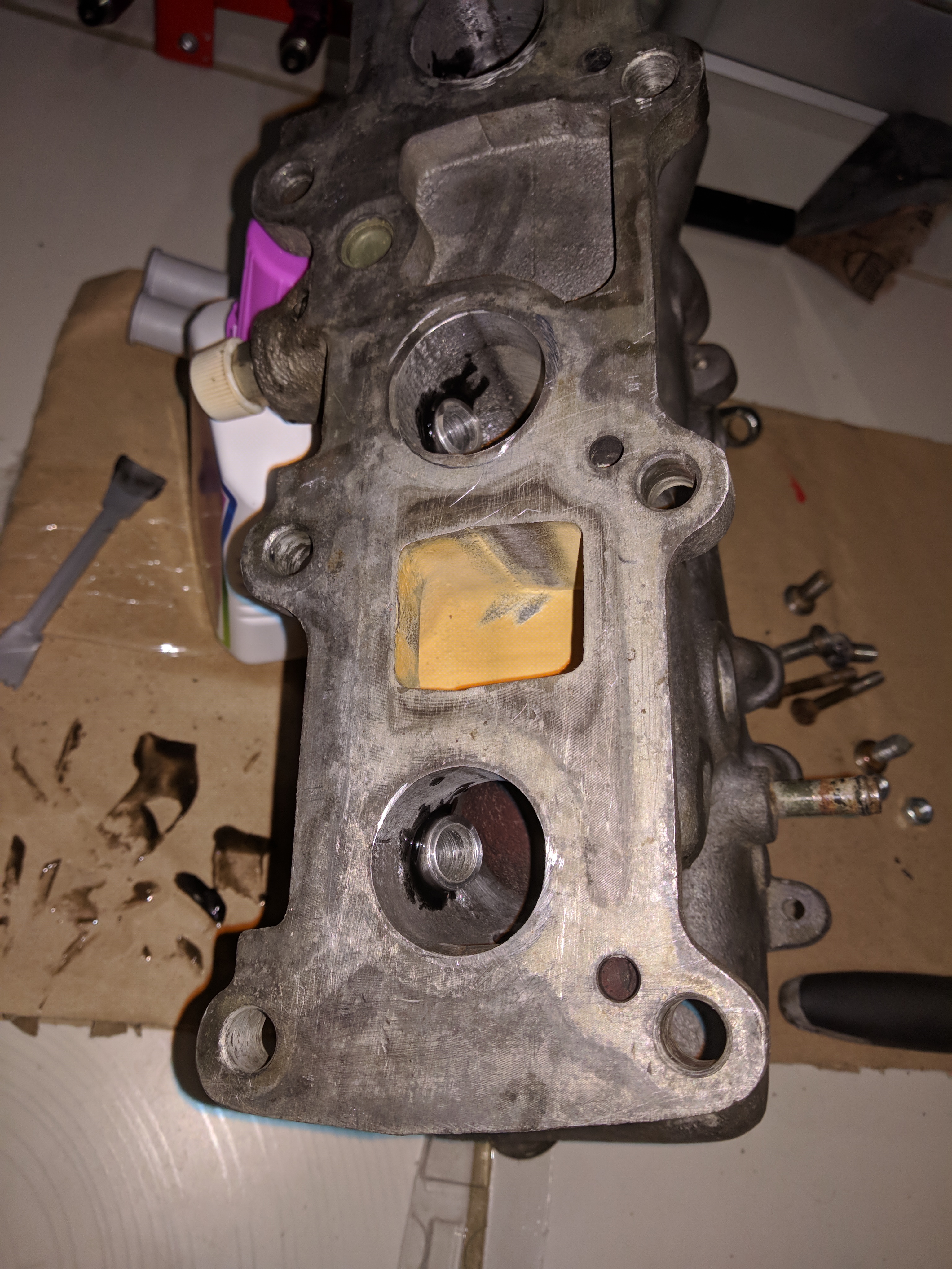
This is an 8 valve version of the G13, that means the original intake manifolds are only for carburetors and throttlebody injection. Unlike the 8 valve G10, there are no
injectors ports on the head. Drilling out ports in the carb intake manifold was the easiest solution to this, their angle is limited by the fuel rail position. The angle while not ideal never became a problem.
As I don't have access to an AC TIG welder the injector bungs are epoxied in place, epoxy is applied to the vacuum side, atmospheric side, and the port inside itself. For now they are sealing fine.
Bottom injector seals are TOYOTA 2329122020.
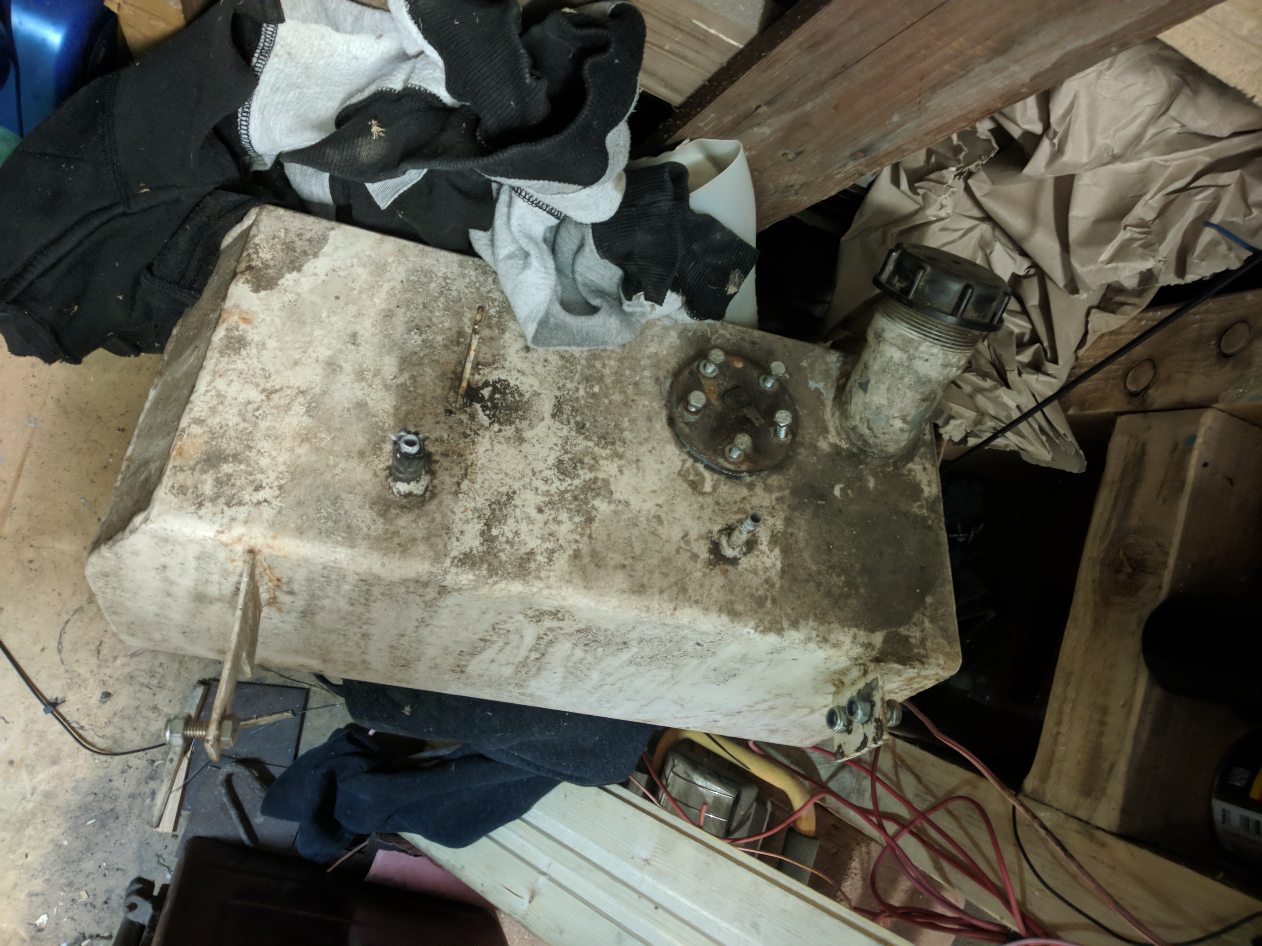
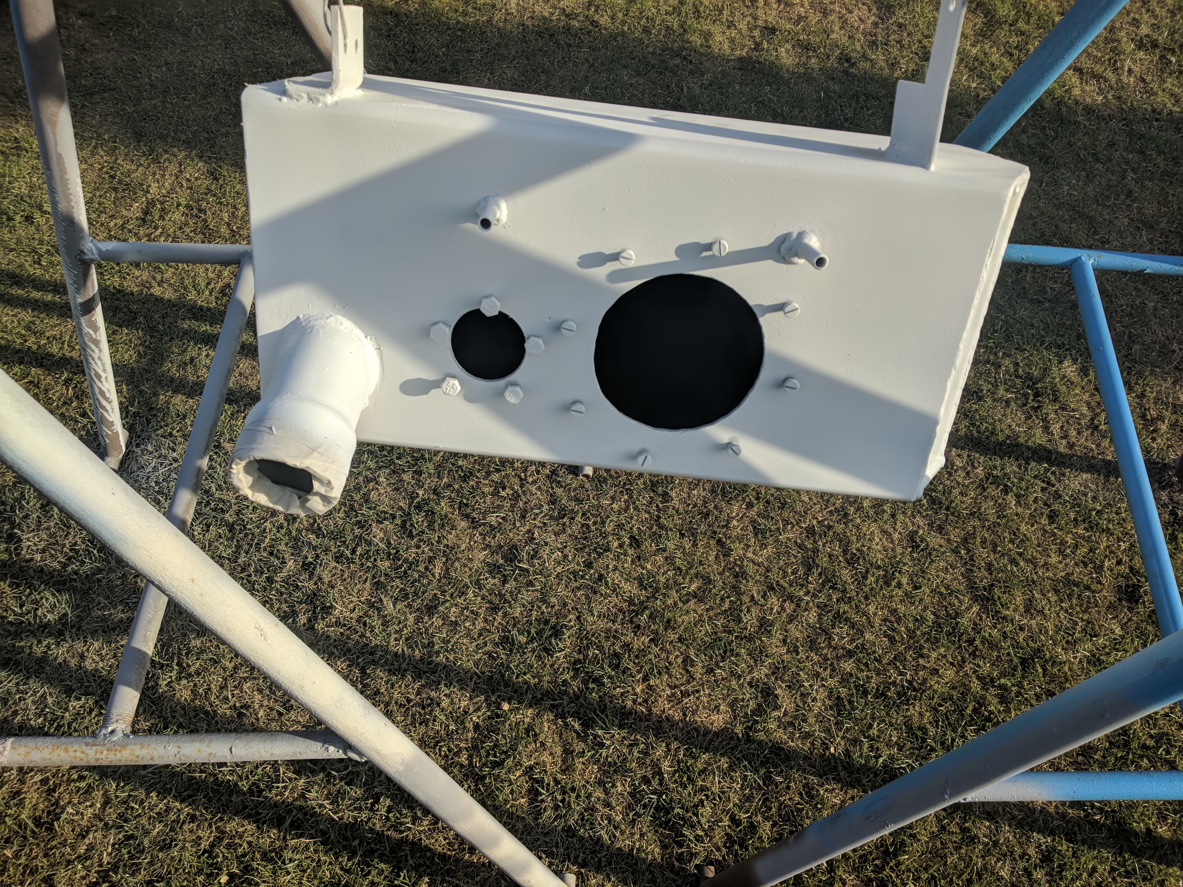
The fuel tank was replaced during the pickup modification, a low pressure fuel pump for the carb was fitted instead of the unreliable mechanical pump.
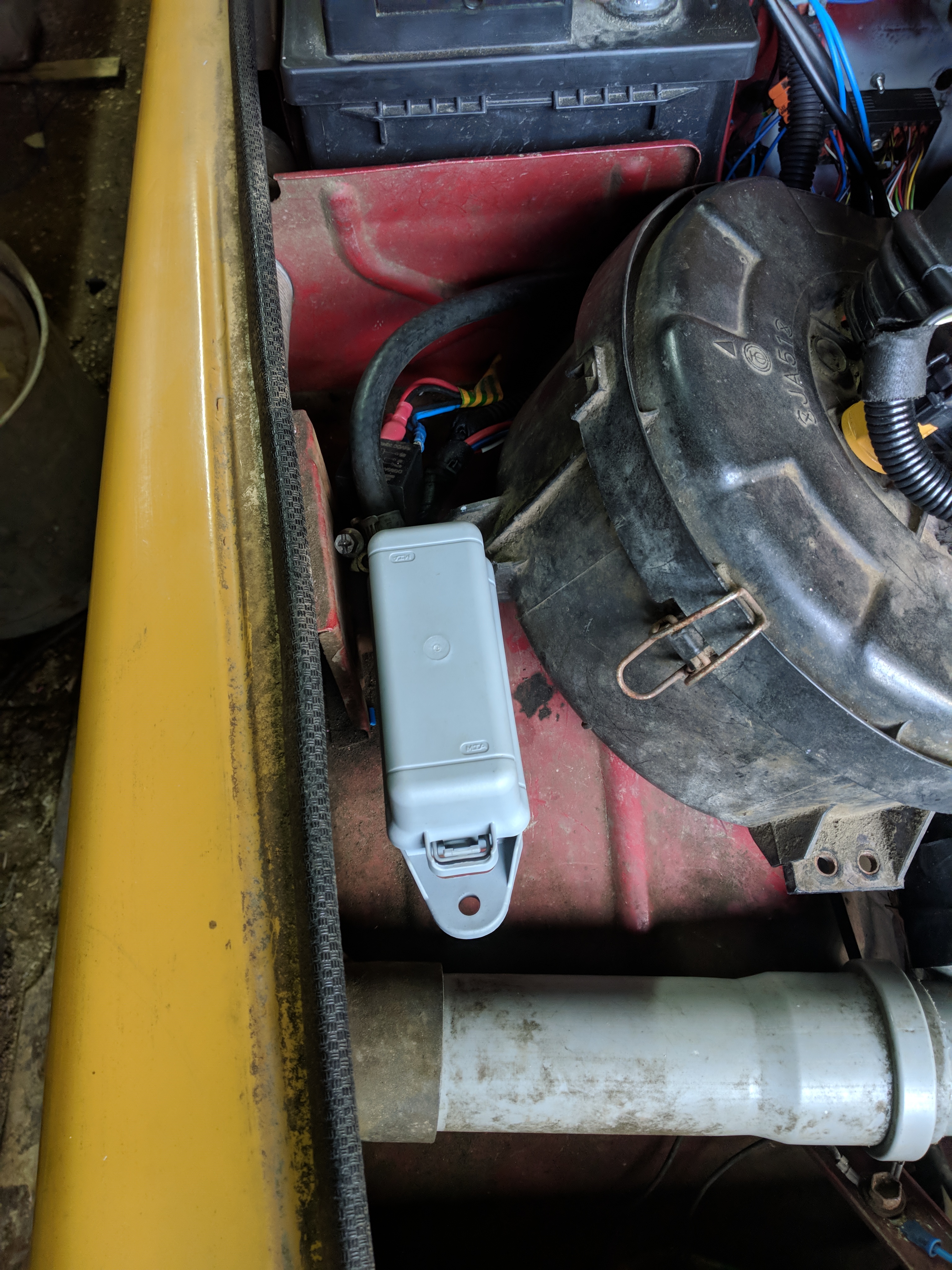
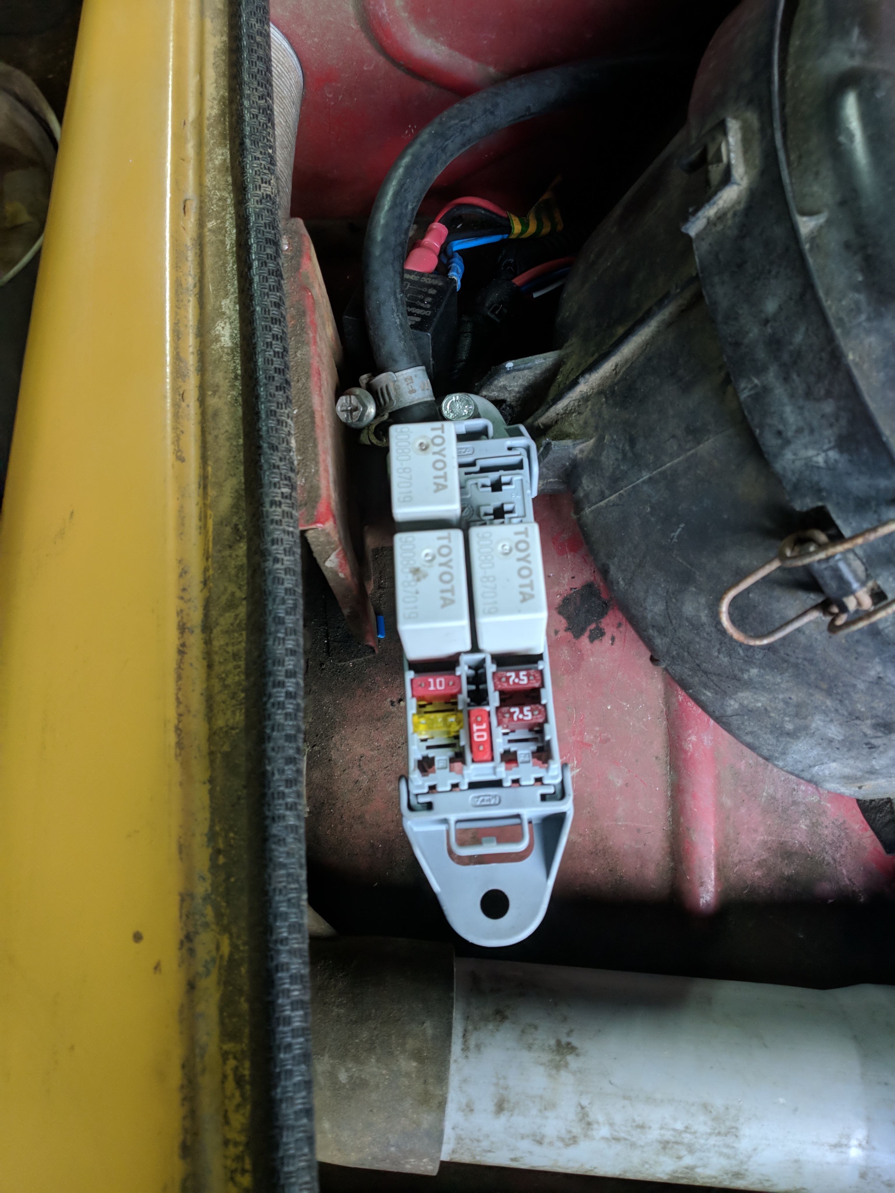
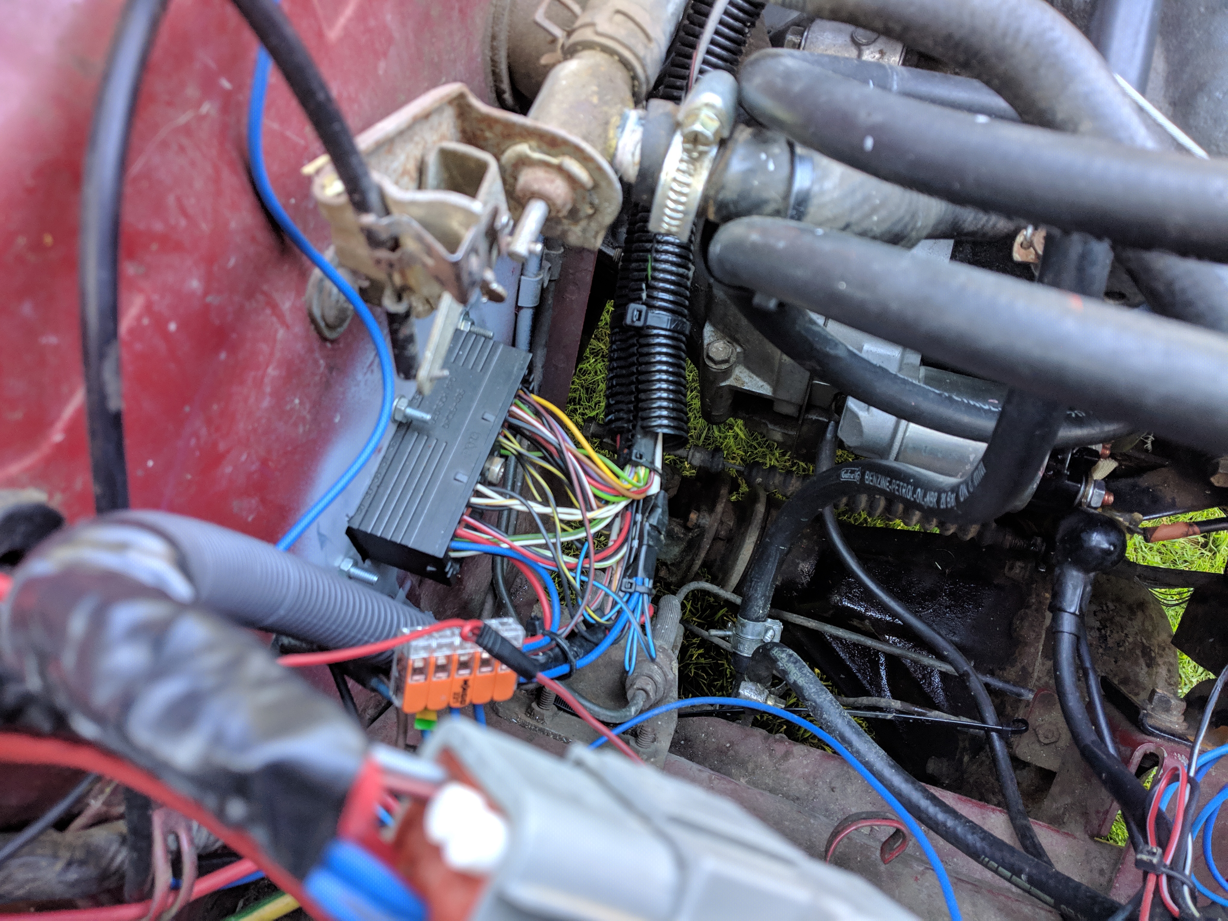
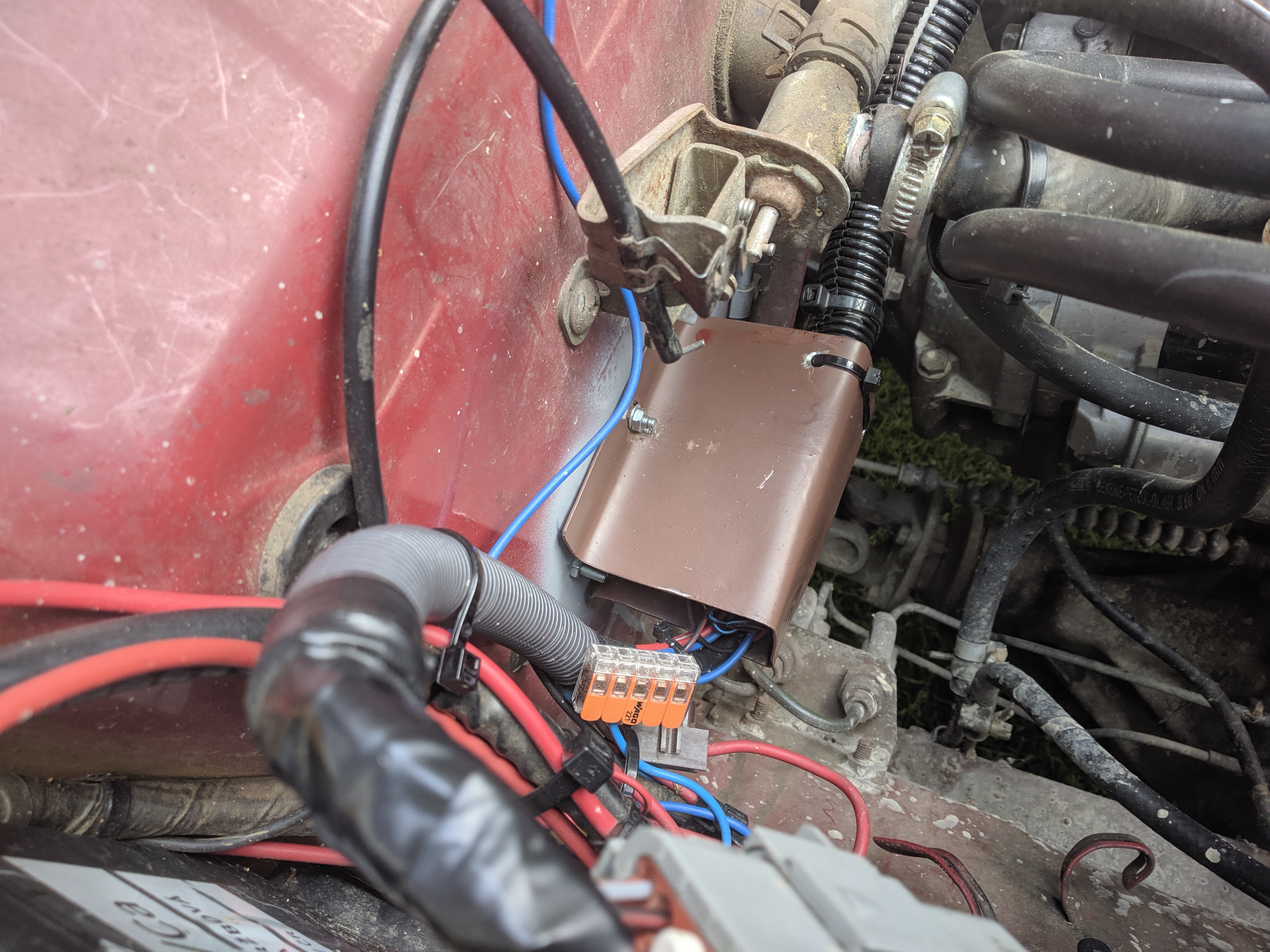
The factory fuse box is extremely basic and doesn't have enough positions for this setup. It utilizes the ancient DIN 72581/1 standard. I added my own
secondary fuse box, a MTA F7-0002-0006. It has 6 fuses, 4 relays, 2 spare fuse positions and uses the more common and newer SAE J1284 Mini standard.
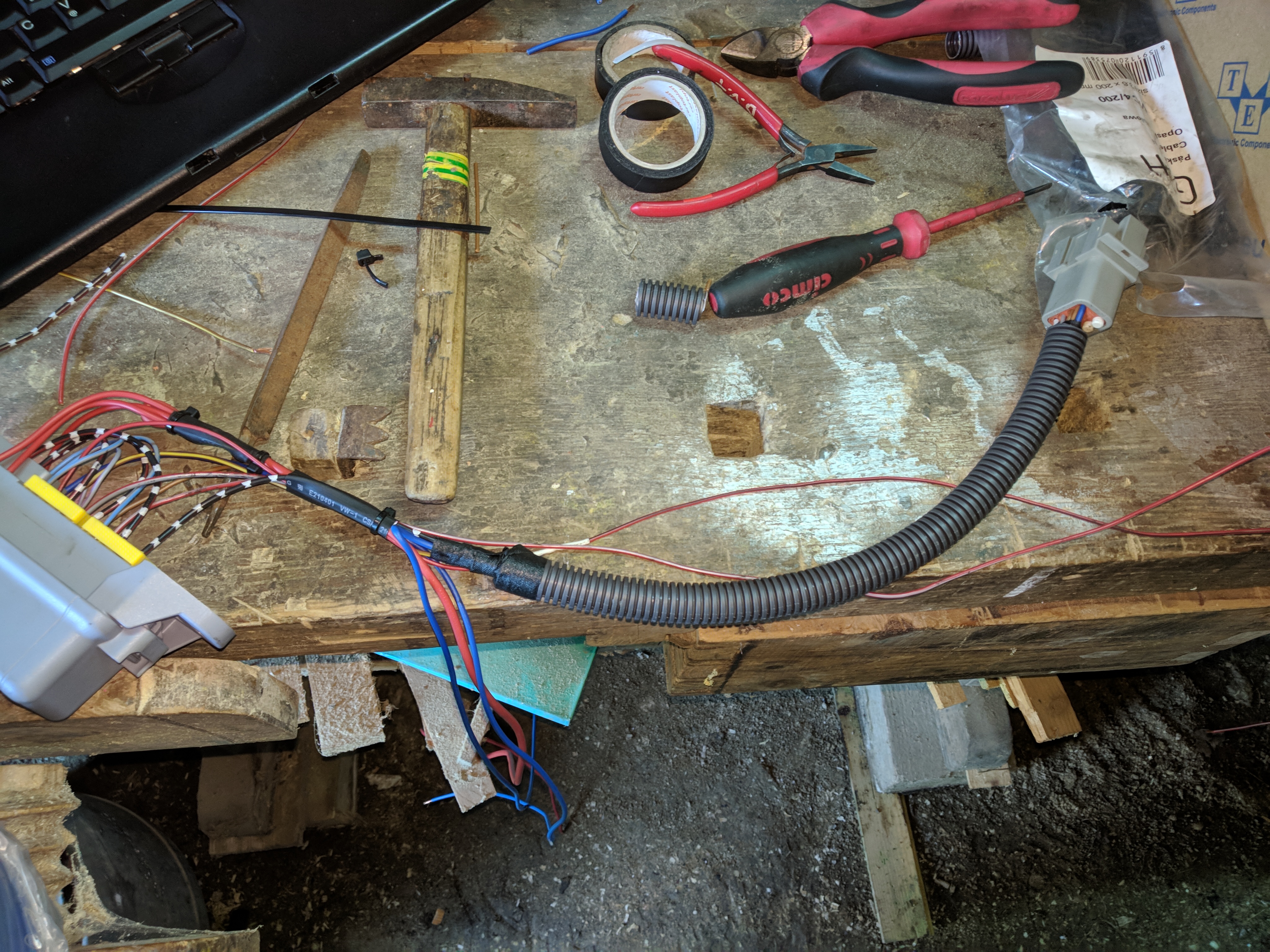
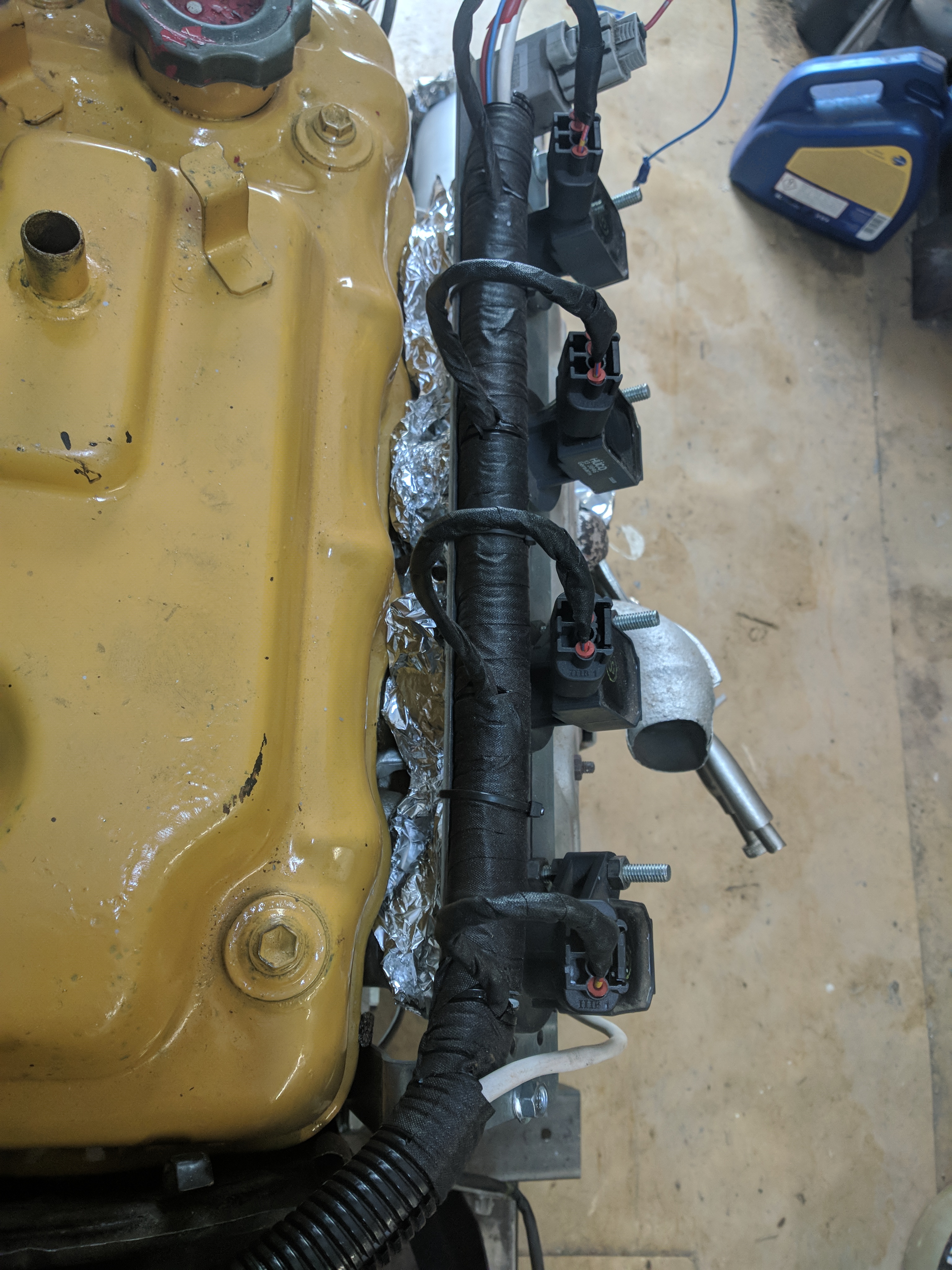
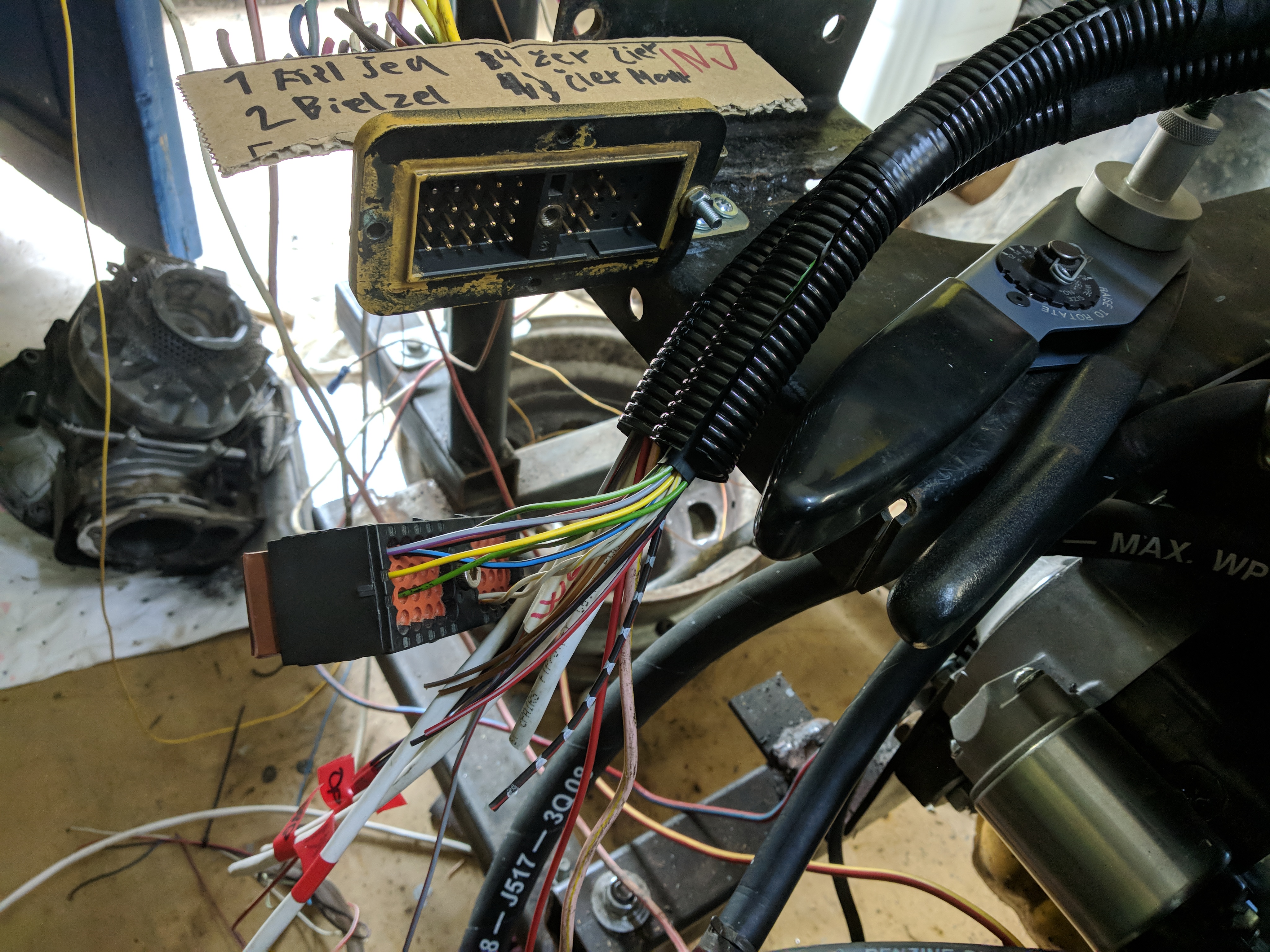
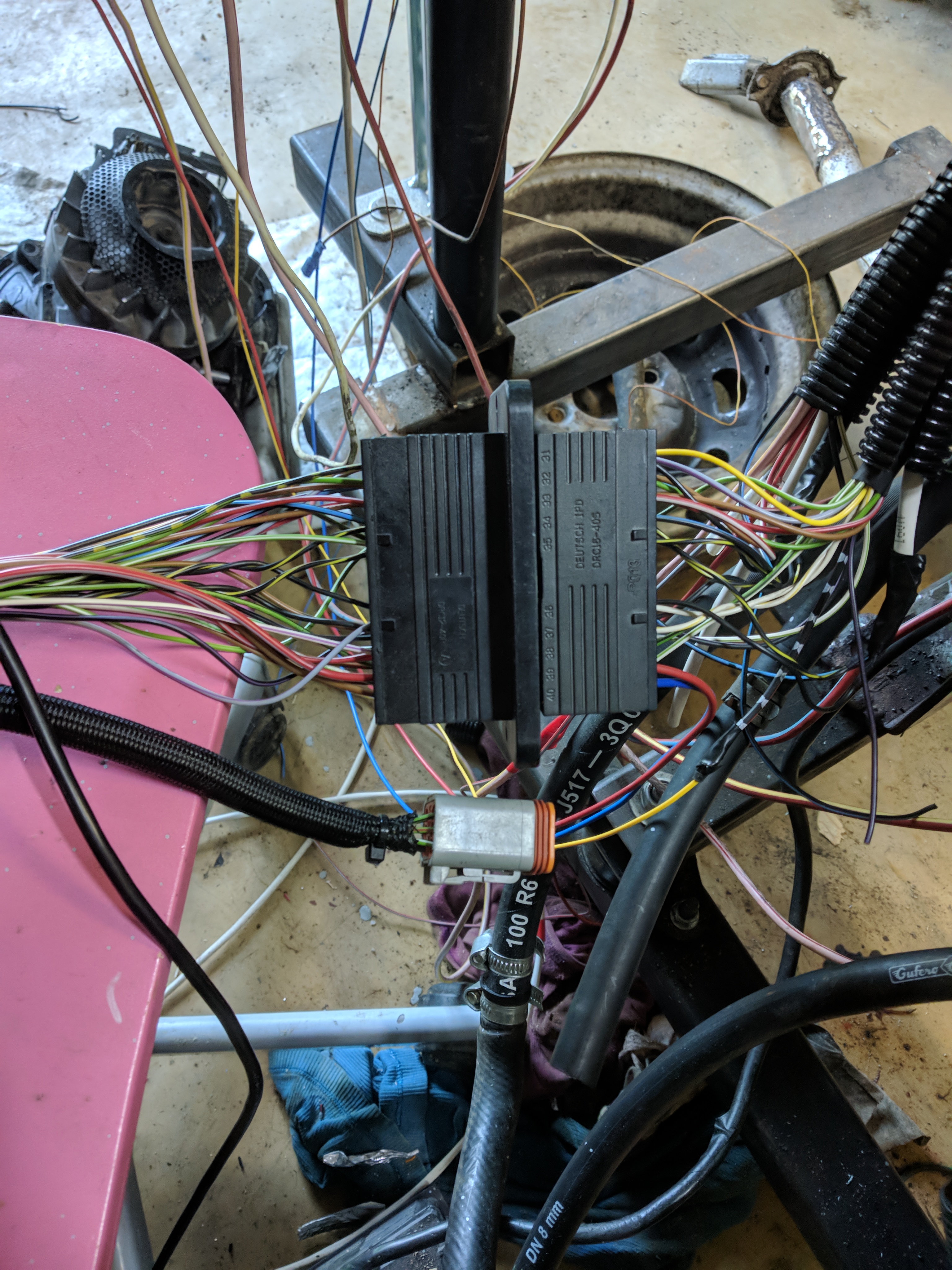
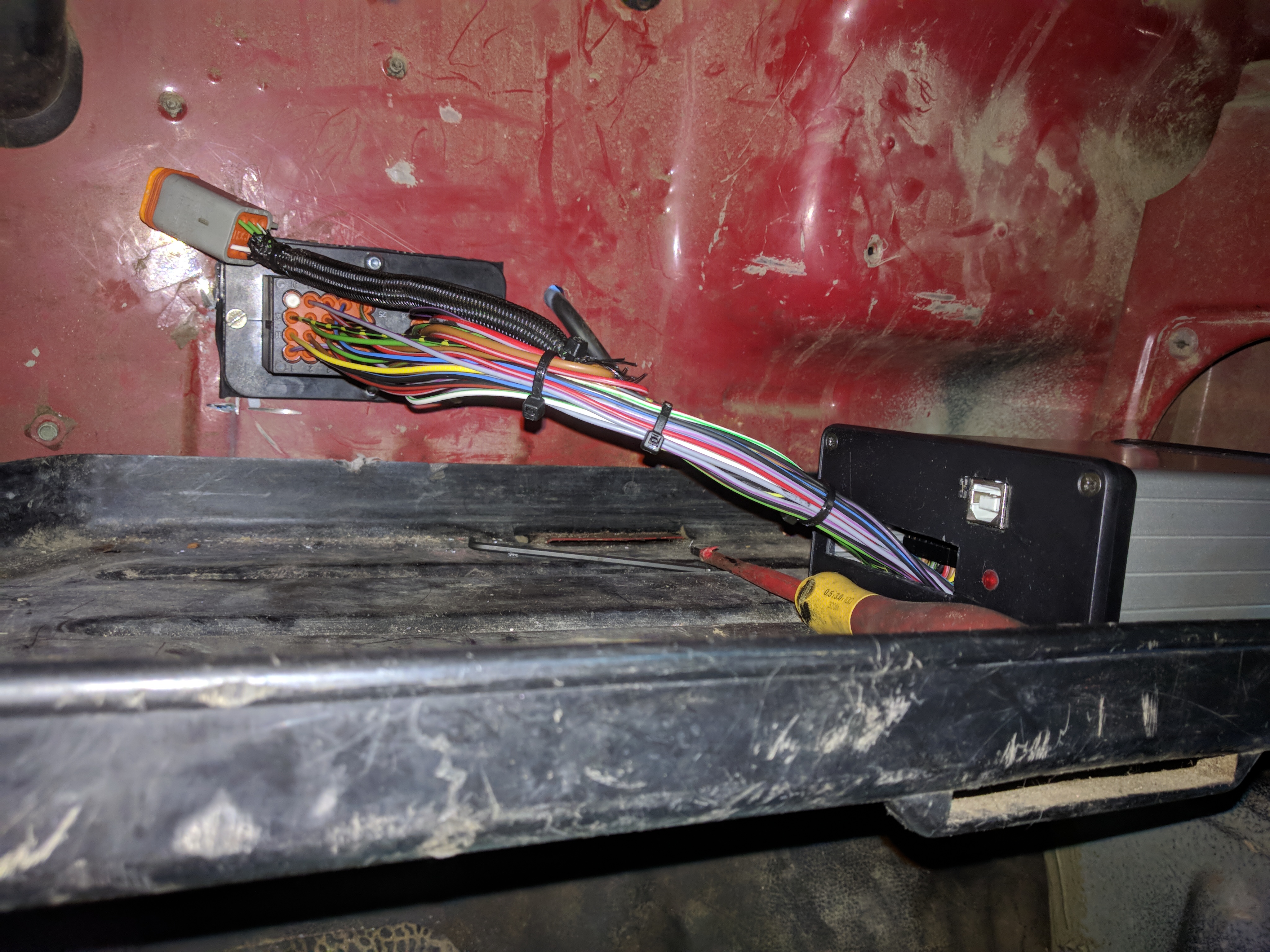
There are many ways to make a wiring harness, in this case I chose to split the intake and exhaust side and route the wiring in conduit. The exhaust side which I made first
contains the ignition, crank position sensor, and TinyWB signals. Intake side contains the fuel injectors, sensors on the throttlebody, temp sensors, and cam position signal. The two halves meet at the
main DEUTSCH DRC16-40S connector which connects to a DRC12-40PA on the firewall. If I was making the wiring harness again I would start from the main connector. In this case i had to start backwards
because I didn't know the position and type of connector that I would be using. This caused a lot of guess work. As soon as I figured out the connector I made a jig on the stand. Thanks to a lot of prep work
the final connector wiring was painless and error-free. All sections of the conduit that have a high chance of getting splashed by mud are covered in tape. Inside, the wiring is zip tied together on
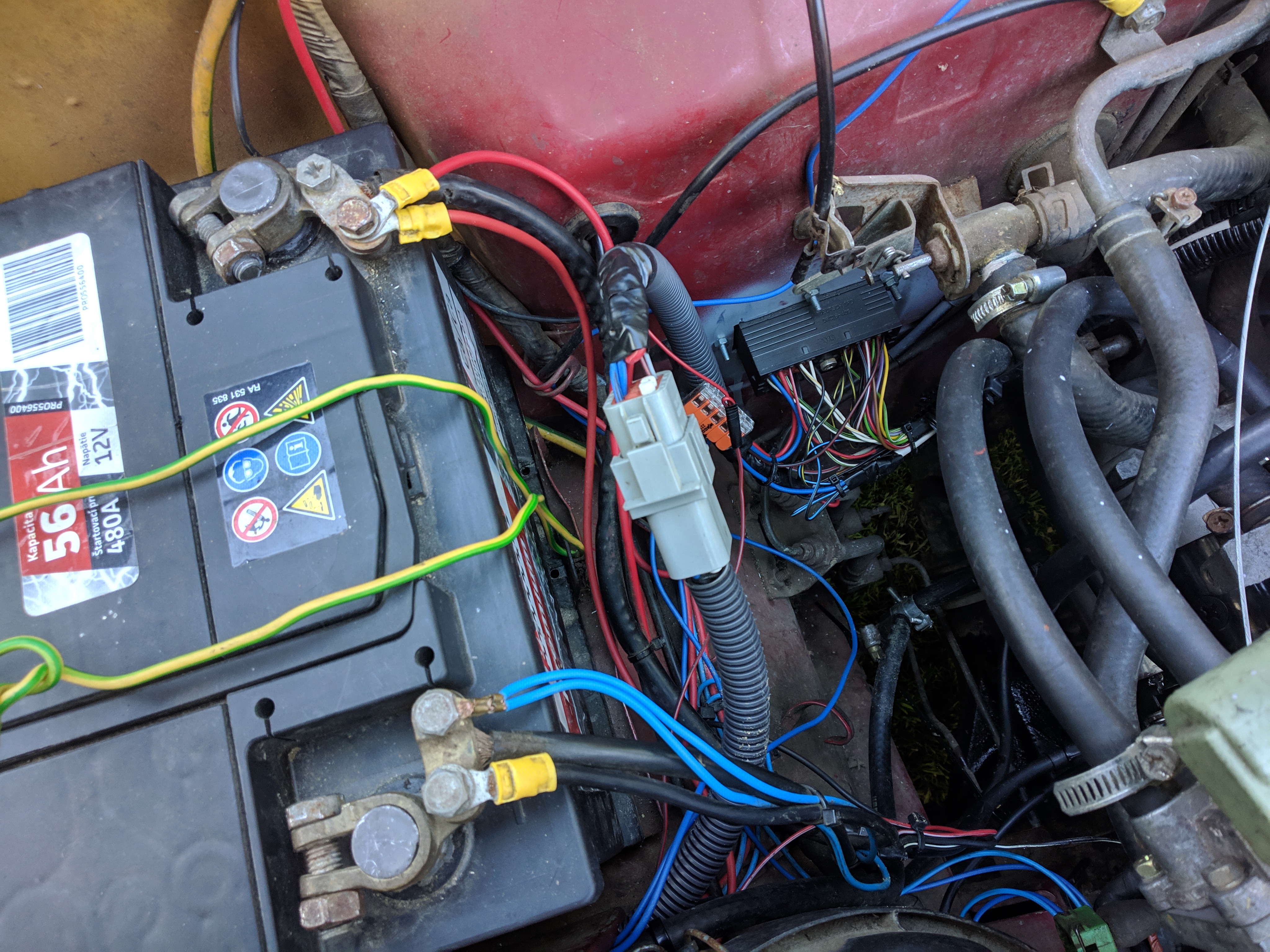
multiple spots, especially around where it exits out. Majority of the wires come from a Mercedes E290TD interior. The power comes directly from the fuse box through an 8 pin connector.
Wiring harnesses are secured to the main connector splash cover.
Page viewed best on a 1200x1600 monitor in Firefox with Terminus font and a dark background