
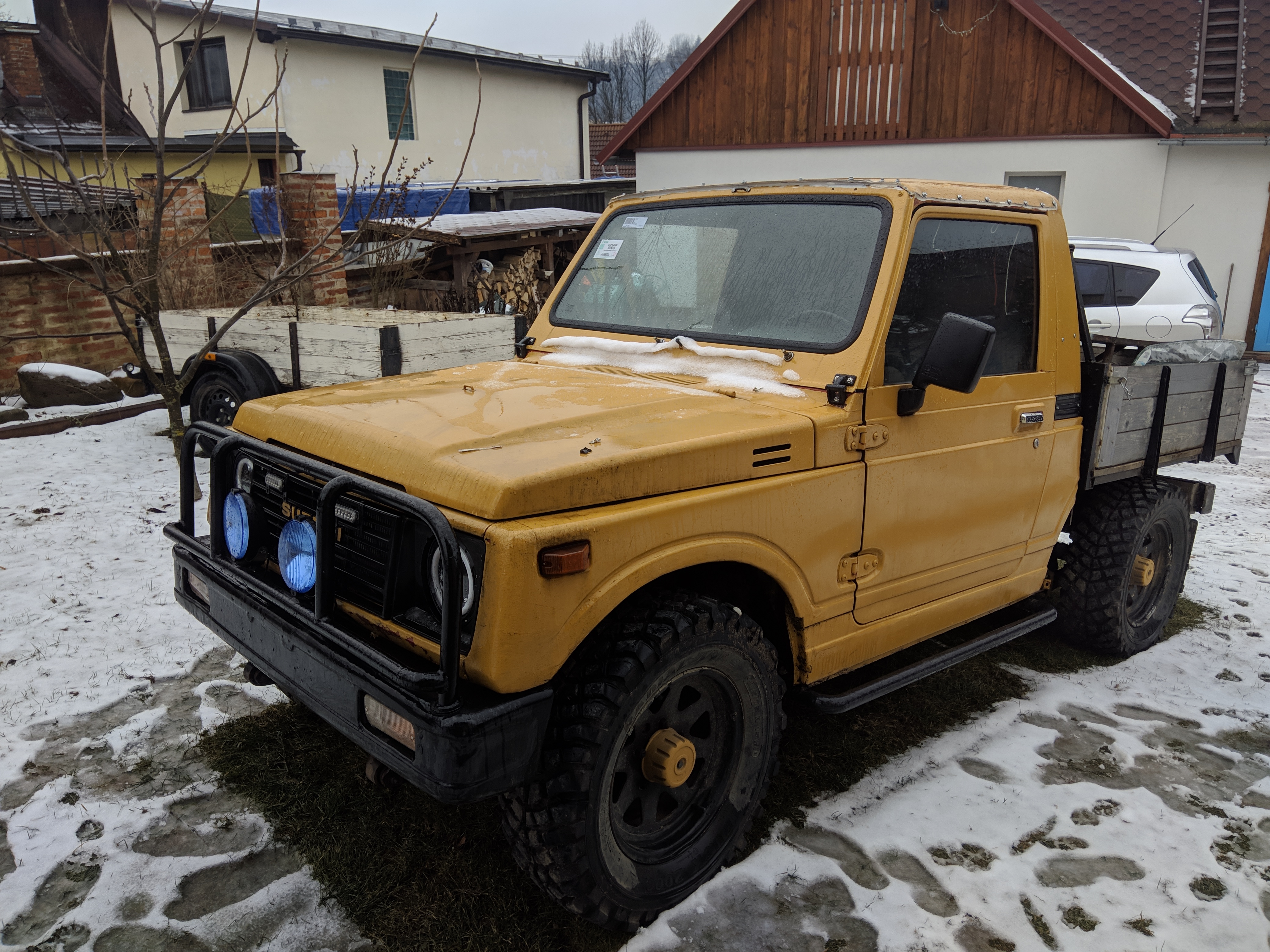
Converting this car to EFI it has improved a ton of things, this being my first EFI rodeo certain issues did come up combined with the fact that this is a 37 year old car it's safe to say maintenance was required.
Let's start with the positives, fuel consumpion has decreased about 3/4 to 1/2 depending on the load. This is awesome, from the logs I estimate around 12L/hour instead of around 20L/hour
During the yearly oil change the oil level has stopped rising, with the carb the oil would get dilluted with fuel from running way too rich. This decreases oil lifespan and makes the lubrication worse.
Cold operation works perfectly, instead of a rich misfire and barely holding an idle it is now a usable vehicle within 15 seconds of it starting up. I'd say that the primary goals were achieved.
Now let's get to what needs to be fixed. As I originally guessed, the throttlebody was way too large and resulted in poor granularity and made tuning acceleration enrichment extremely painful.
Due to having limited tuning time, usually only 1-2 days every 2 weeks the cold starting was poor, once started it ran fine however I and others using the car weren't very satisfied with it.
Valve cover started leaking again, rubber plugs of the bolts holding the cover were on their last legs. I'd love to get an aluminium cover from a Subaru Justy, but they are bit uncommon.
I wasn't happy with how the ECU was mounted and connected, it was just zip tied in the tray and disconnecting it from the car required disassembly.
Shortly after installing the EFI system I made a temporary instrument cluster, however it had only the bare essentials and I liked the factory cluster much more.
We also thought about mounting a turbocharger, these engines are quite stout and can take it. I did a lot of research, and purchsed the parts however stopped
in the middle of the installation because of engine health, I will elaborate on this point furhter on. The result was a cylinder head replacement.
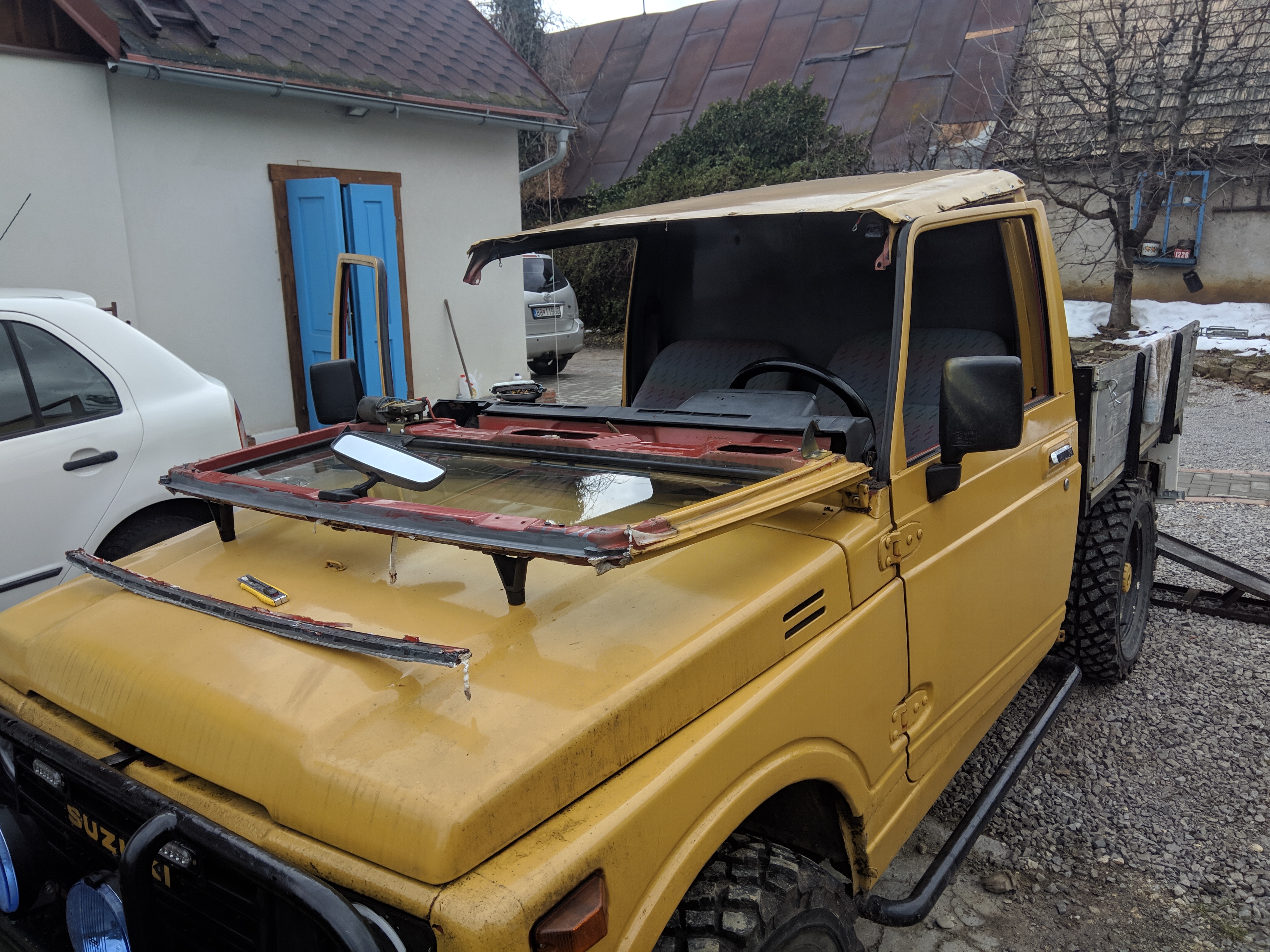
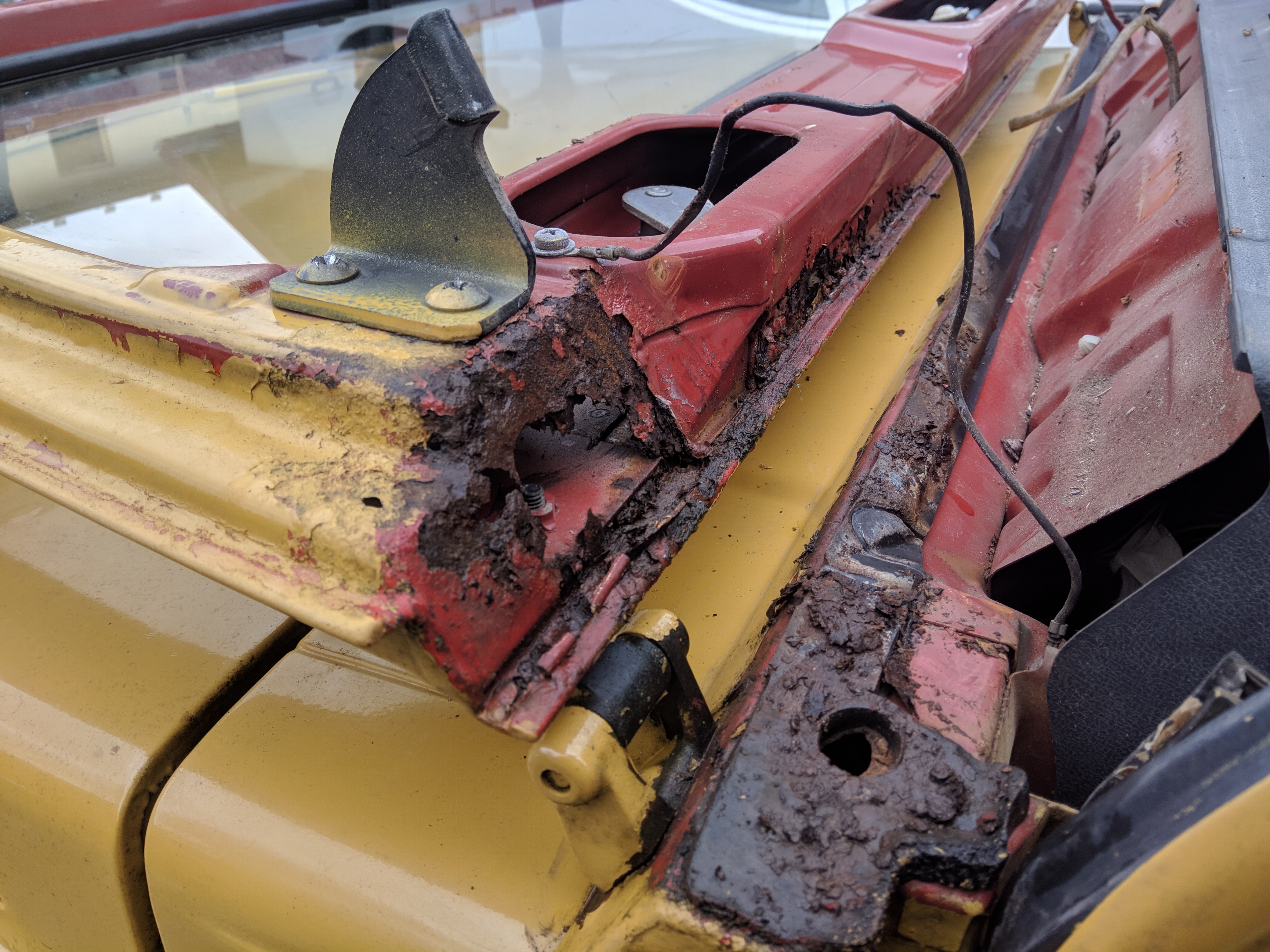
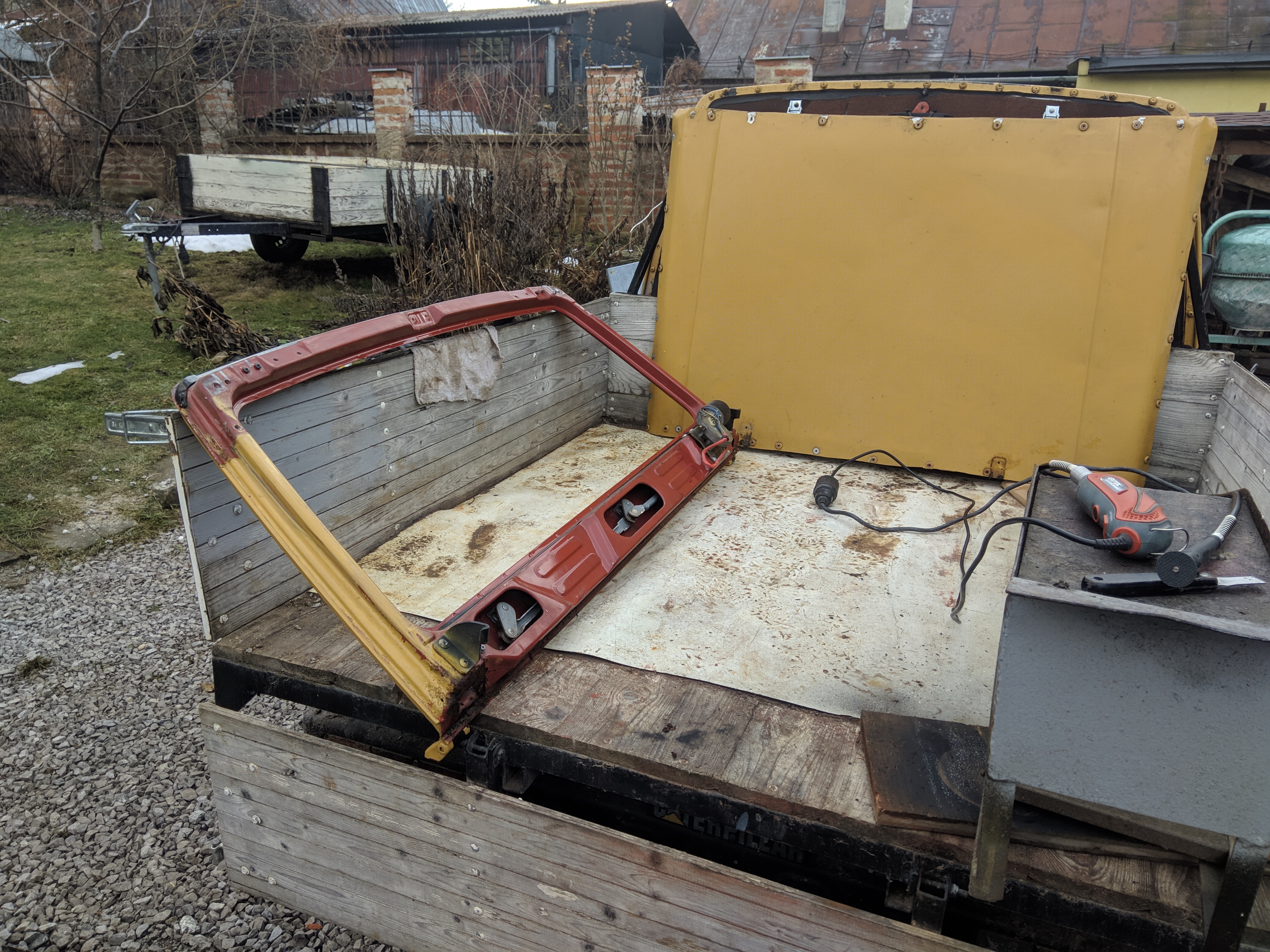
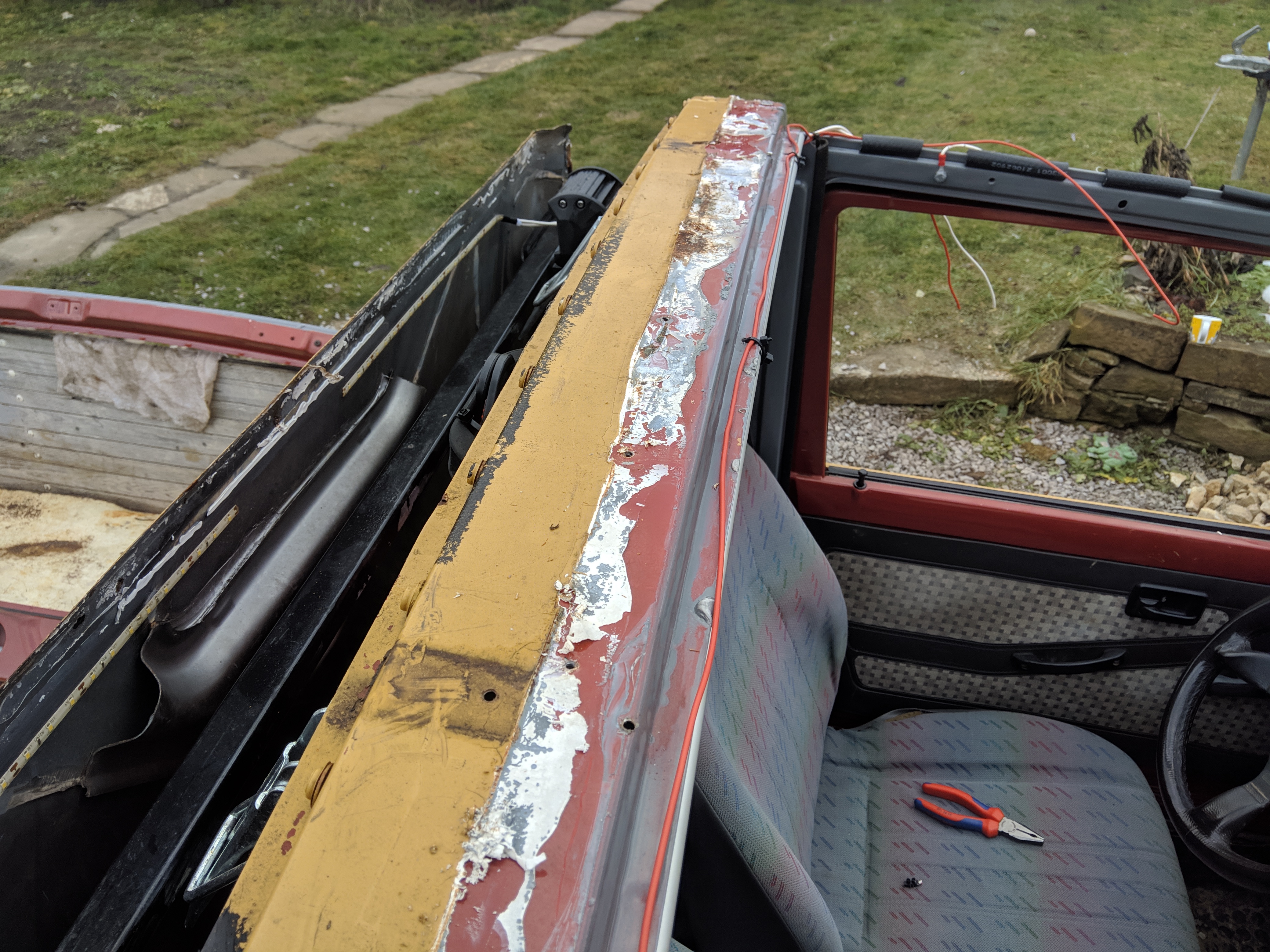
We discovered a water leak into the interior whenever the car was parked outside and it rained heavily, at first I thought it was a roof leak but it ended up being a windshield frame leak.
Goals of this revision are:
Improving cold start
Low throttle granularity
Transient throttle behavior
Valve cover reseal
Create a better mount for the ECU
Fix the interior water leak
Fix the heater valve cable
Replace cracked windshield
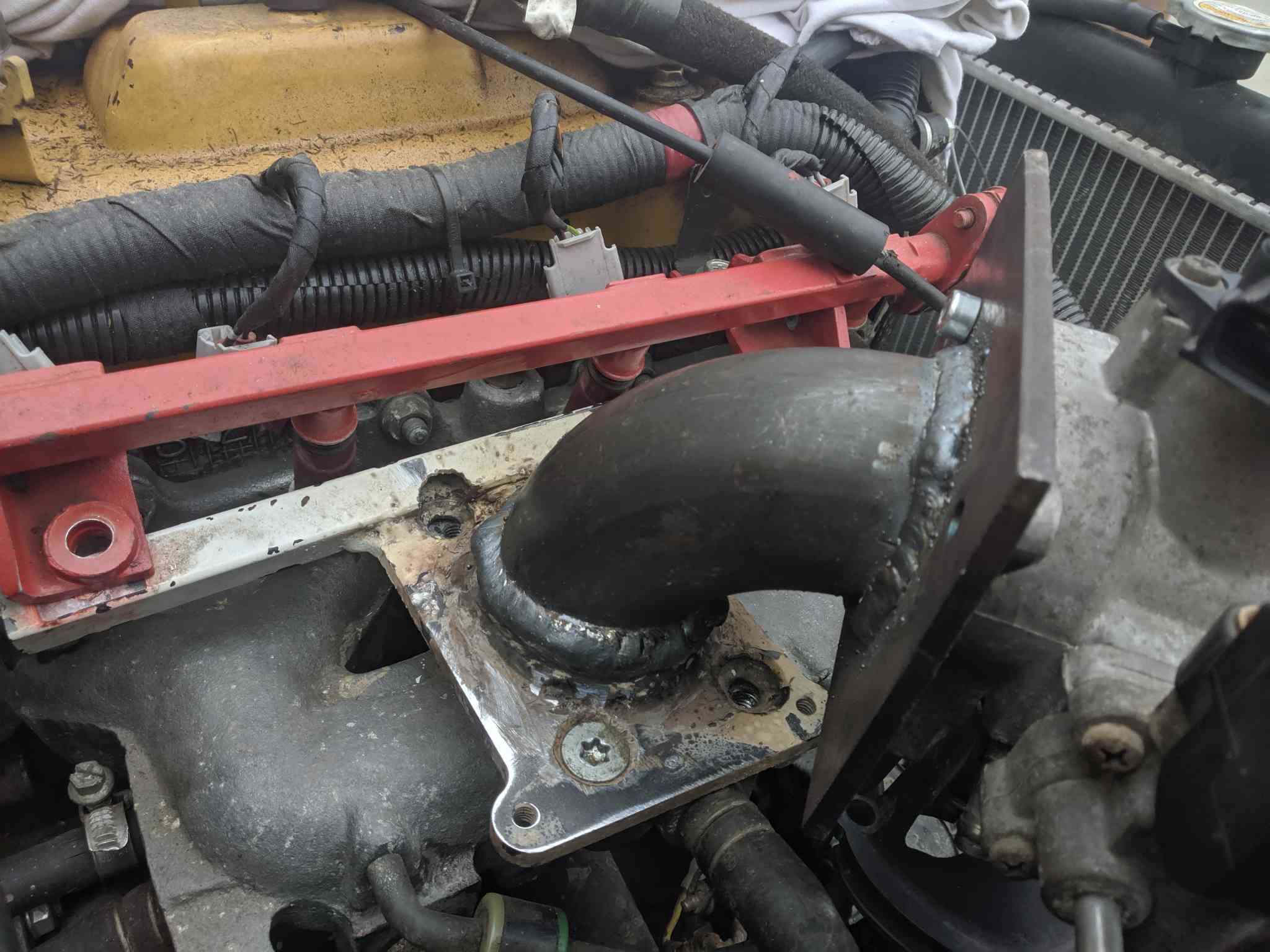
Fix a minor coolant leak on the intake manifold
Integrate a multifunction display into the factory cluster
Replace worn suspension bushings
Fix brakes that often got stuck
Fix battery drain
Fix transmission leak
Install oil pressure sensor
Install a turbocharger
Fix bullbar rust
Fix bumper rust
Clean seats
Fix seat mounting
Fix exhaust leak
As before, we have to collect the necessary parts before working on it.
Required components:
Exhaust with resonator
Correctly sized throttlebody
Minor gaskets, seals
Intercooler
Turbocharger
Cylinder head
LED lights
ECU faceplate with connectors
Various materials for wiring
Oil pressure sensor
Windshield
Door seals
Windshield frame seal
Winshield seal
Components to make the instrument cluster
Brake caliper rebuild kit
Let's get the boring stuff out of the way, yearly oil change, replace the spark plugs were left in there from testing. All new door seals, and window channel seals to fix the window 'dinging' that drove me crazy.
Rebuild calipers and replace brake pads, install the new exhaust, and make a proper exhaust bracket as the old one broke. Battery drain was caused by the fuel pump relay coil, the switch for it had a permanent power supply.
Reseal the transmission shift tower that someone previously assembled with no sealant, replace suspension bushings.
Bumper was taken off, my father did the body work, fixing the pinholes in the bumper, replacing a rotten tube on the bullar. Heater valve cable had damaged mounting and the valve was also getting stuck. Ended up replacing it
with a valve in the engine bay. Now that we're in the engine bay, let's investigate the coolant leak, one coolant leak came from the threads of a coolant bleed valve, and another came from
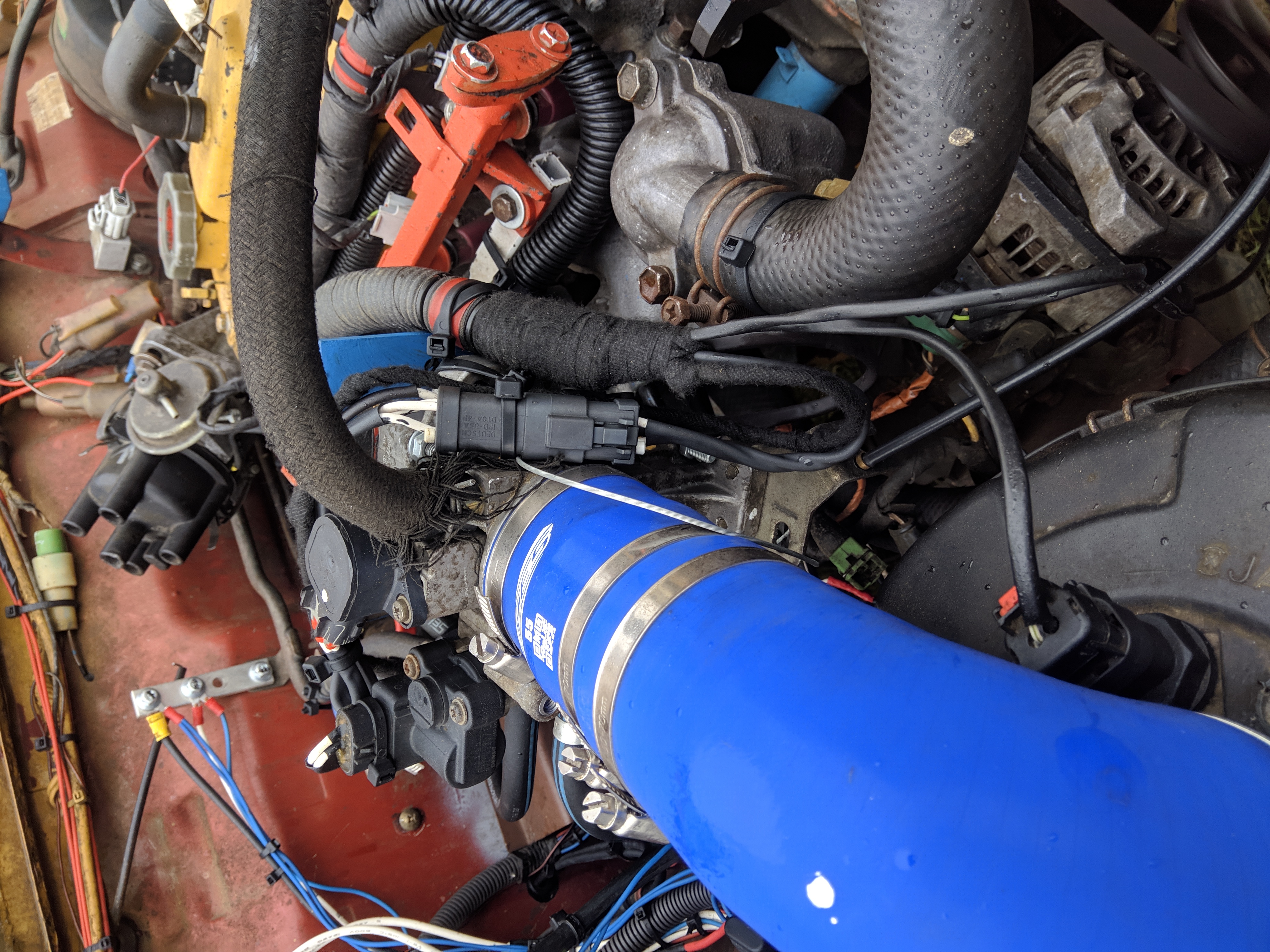
the intake manifold underside where we forgot to tighten a nut on one of the mounting studs last time around. Afterward we started mounting the intercooler, and making space for the turbocharger.
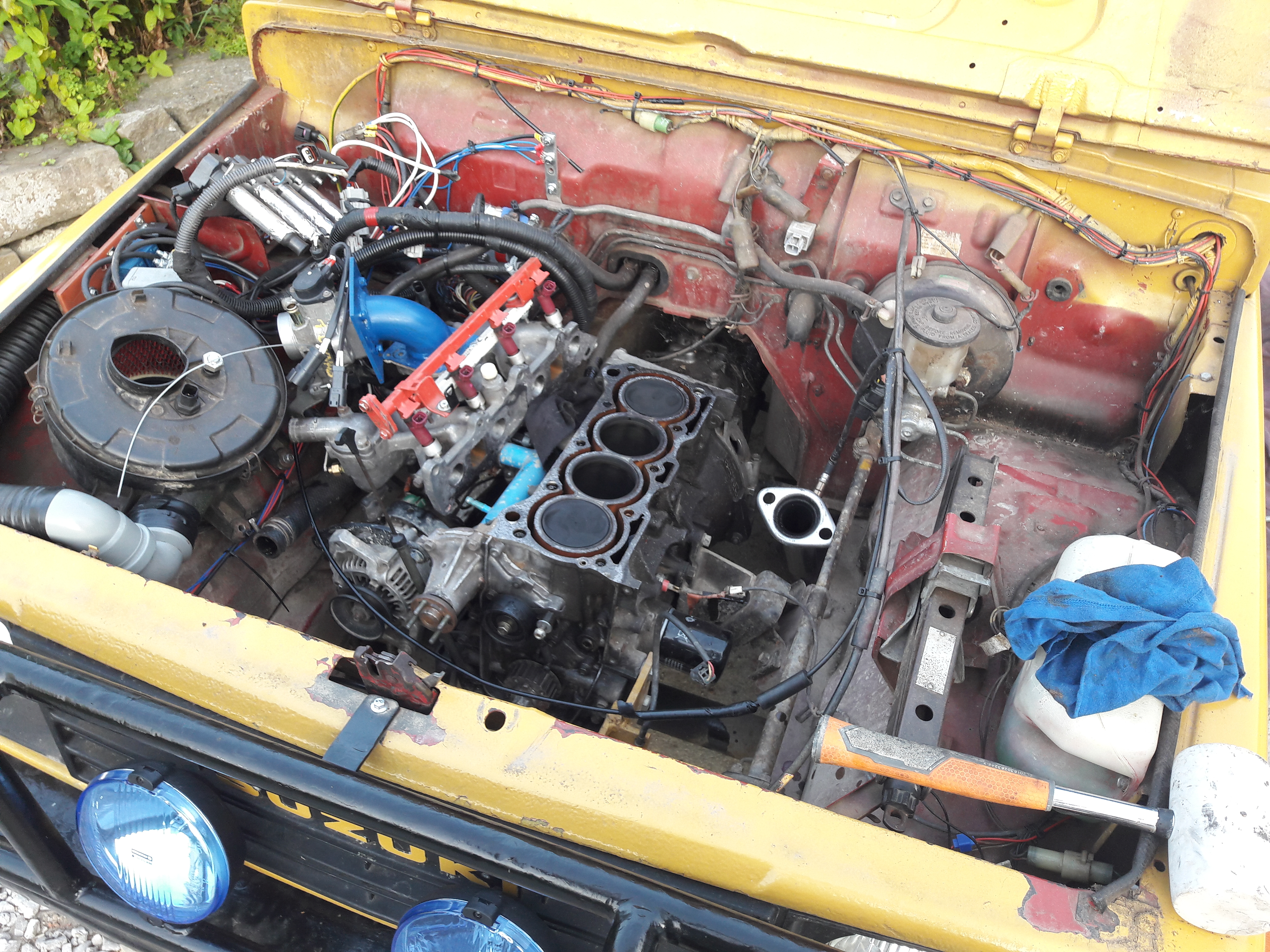
While doing this we also decided to reseal the valve cover and while it was off I discovered a large issue. The camshaft was significantly worn, this seems to be a common thing for this 8 valve model
and was only made worse by the years of having dilluted oil. After searching around for a while the best option ended up buying a lightly used cylinder head that had very little wear.
This cylinder head ended up being cheaper than a new camshaft and overall was in better condition than the one I had, with some cleaning, new valve stem seals, valve lapping, and a resurface at the machine shop
it was ready to be installed. By having the car at home I did manage to get the cold starting to a point where I am happy with it.
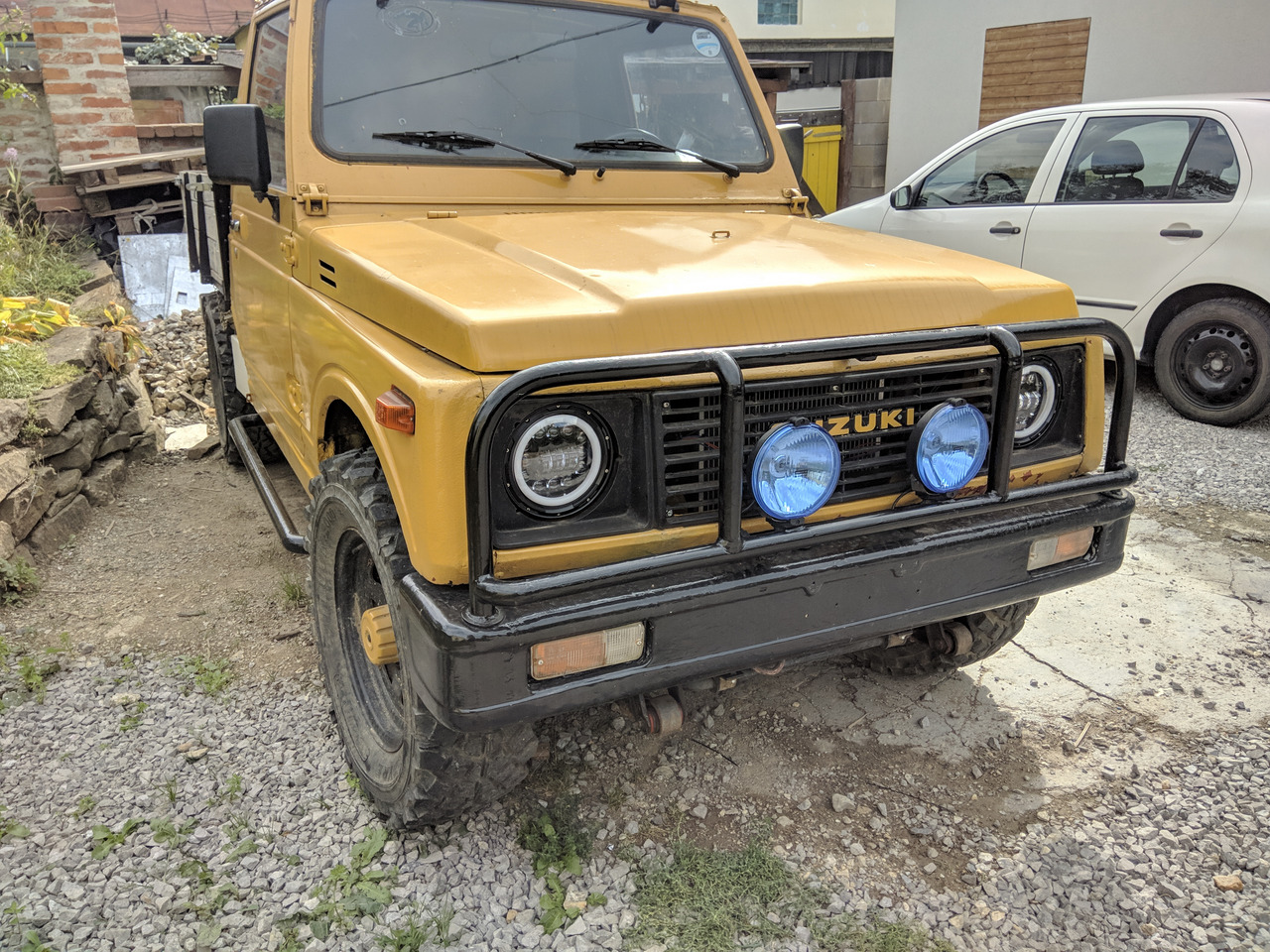
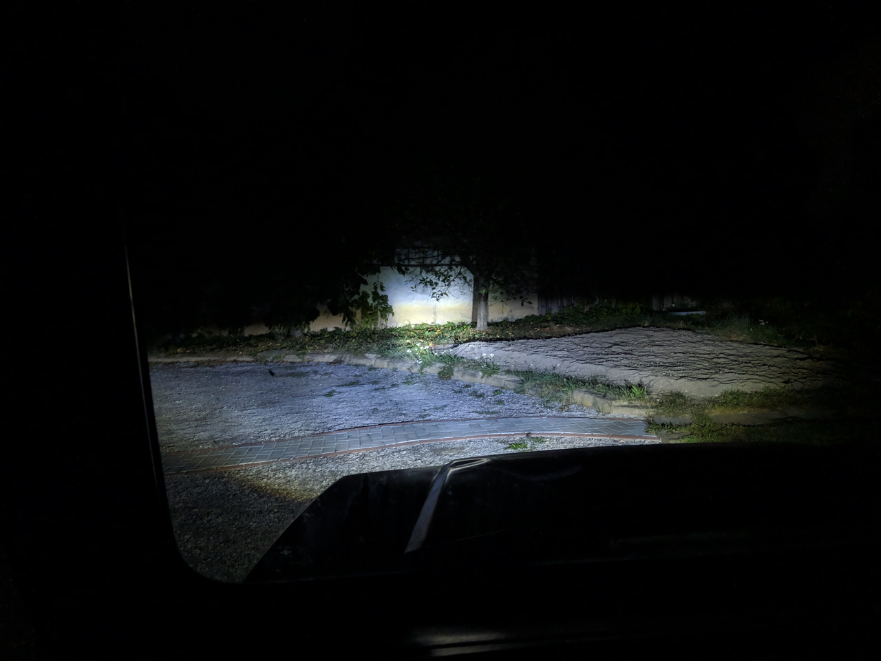
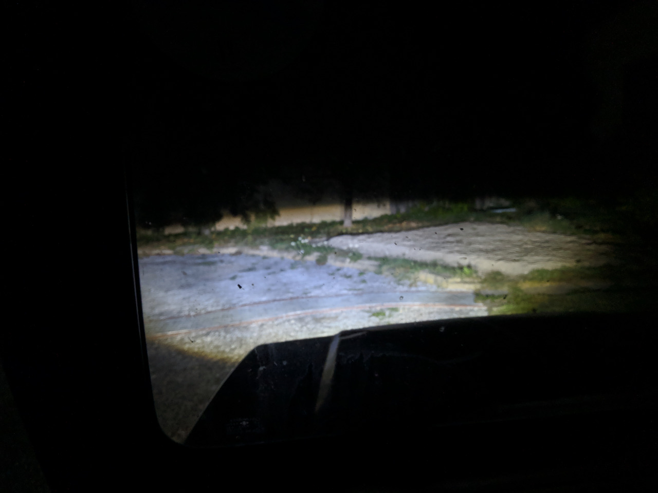
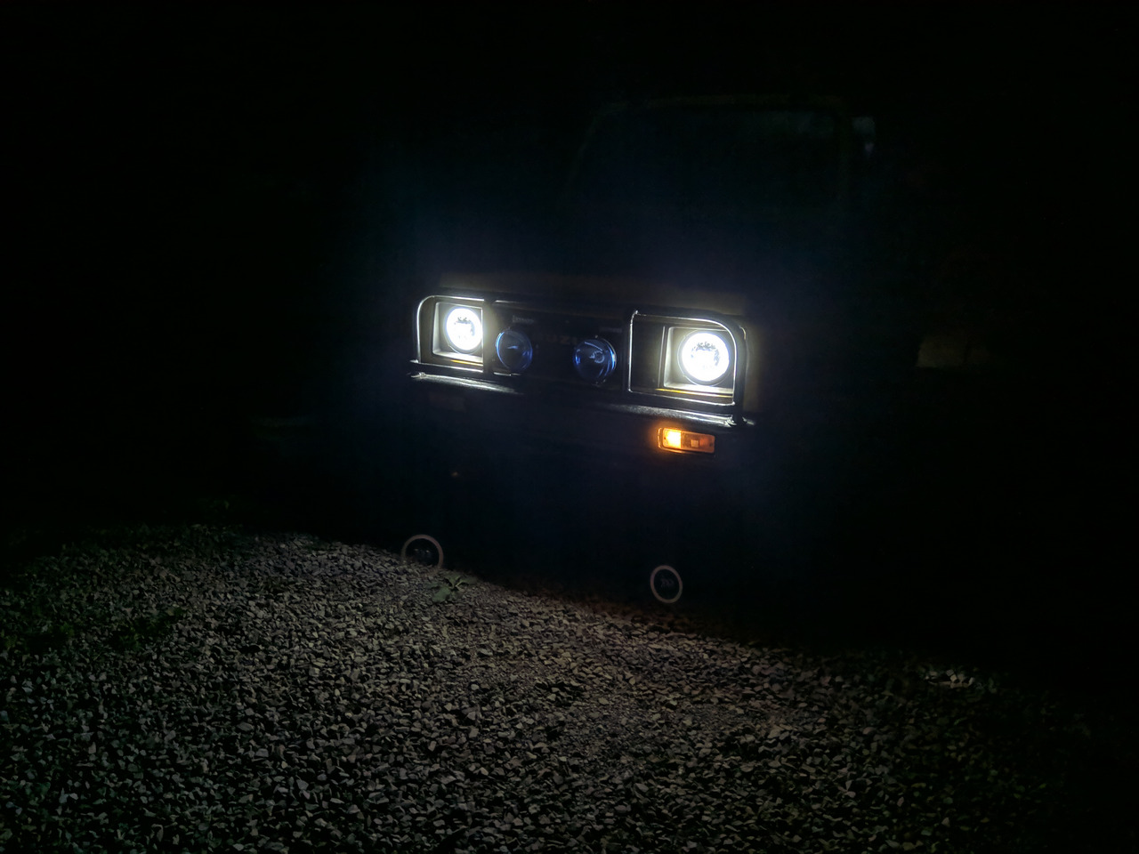
Along the way we decided to mount some LED headlights, they are a standard 7" form factor. The upgrade was well worth it, they work and look awesome.
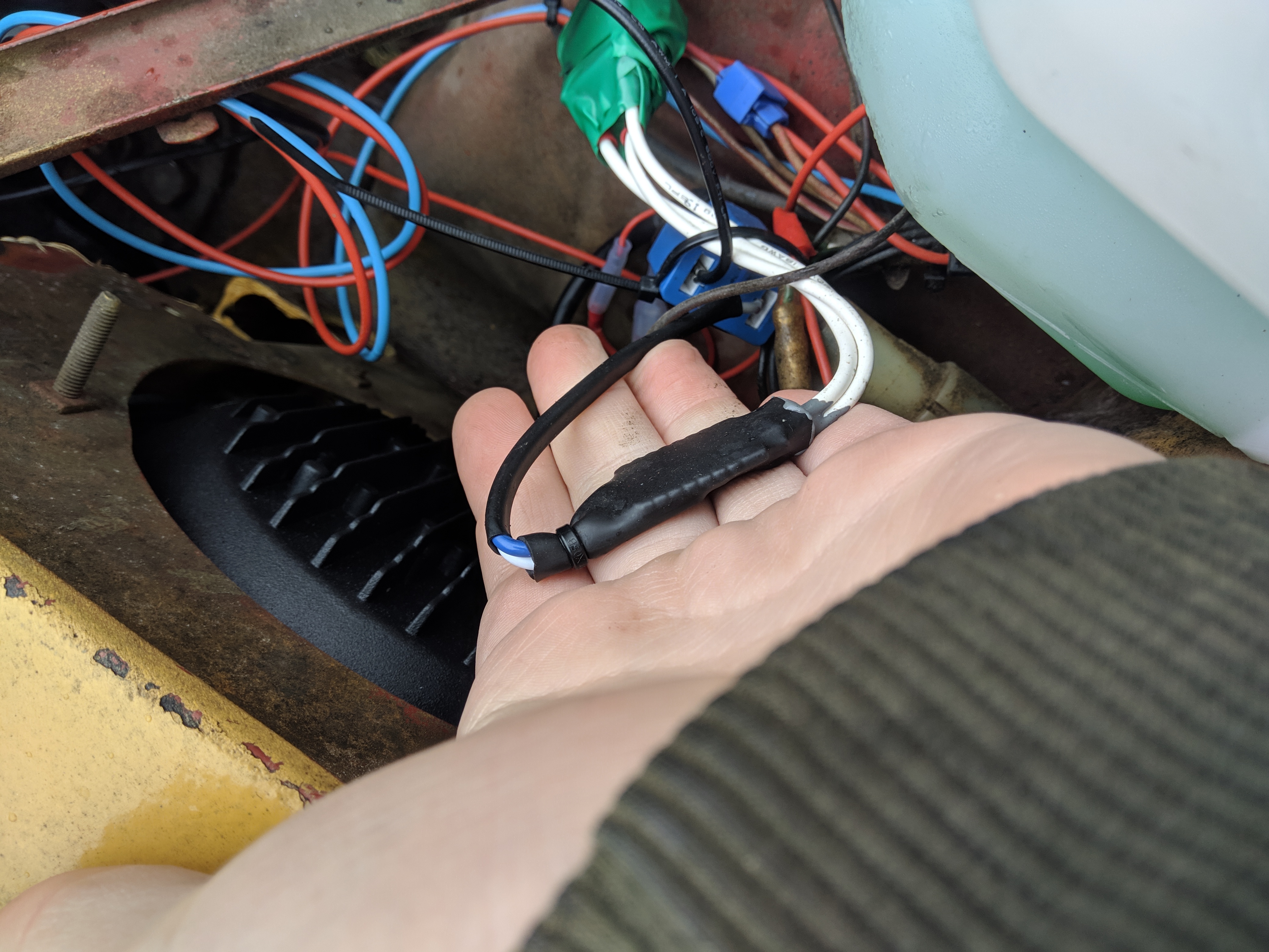
They did not work out of the box, this is because the factory wiring runs a permanent 12V to the common and switches the fillaments on by grounding them. This set of LEDs doesn't support this
I made an adapter that 'inverts' the signal and makes it work properly. They can also be purchased online, but I already had all the parts needed.
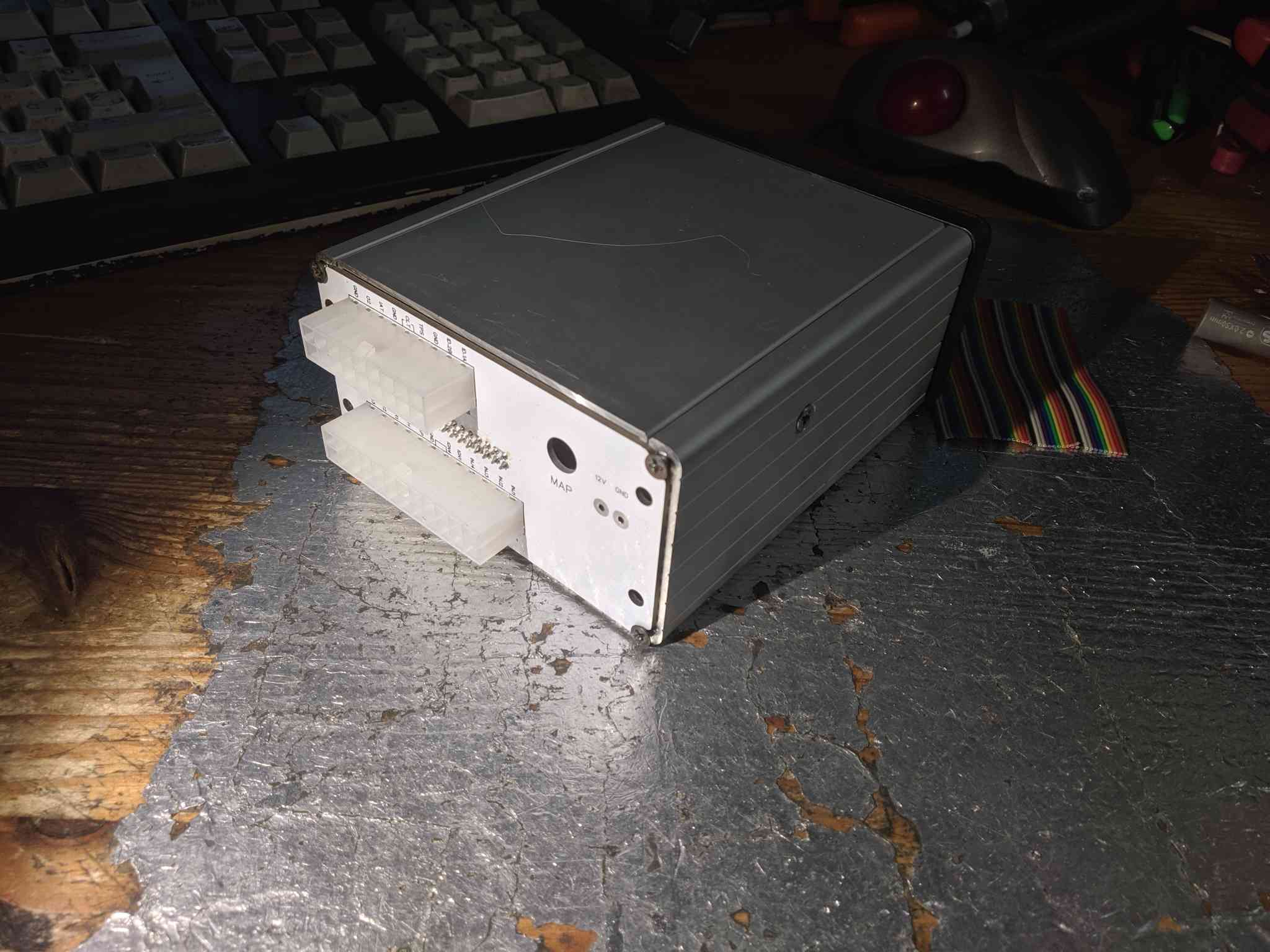
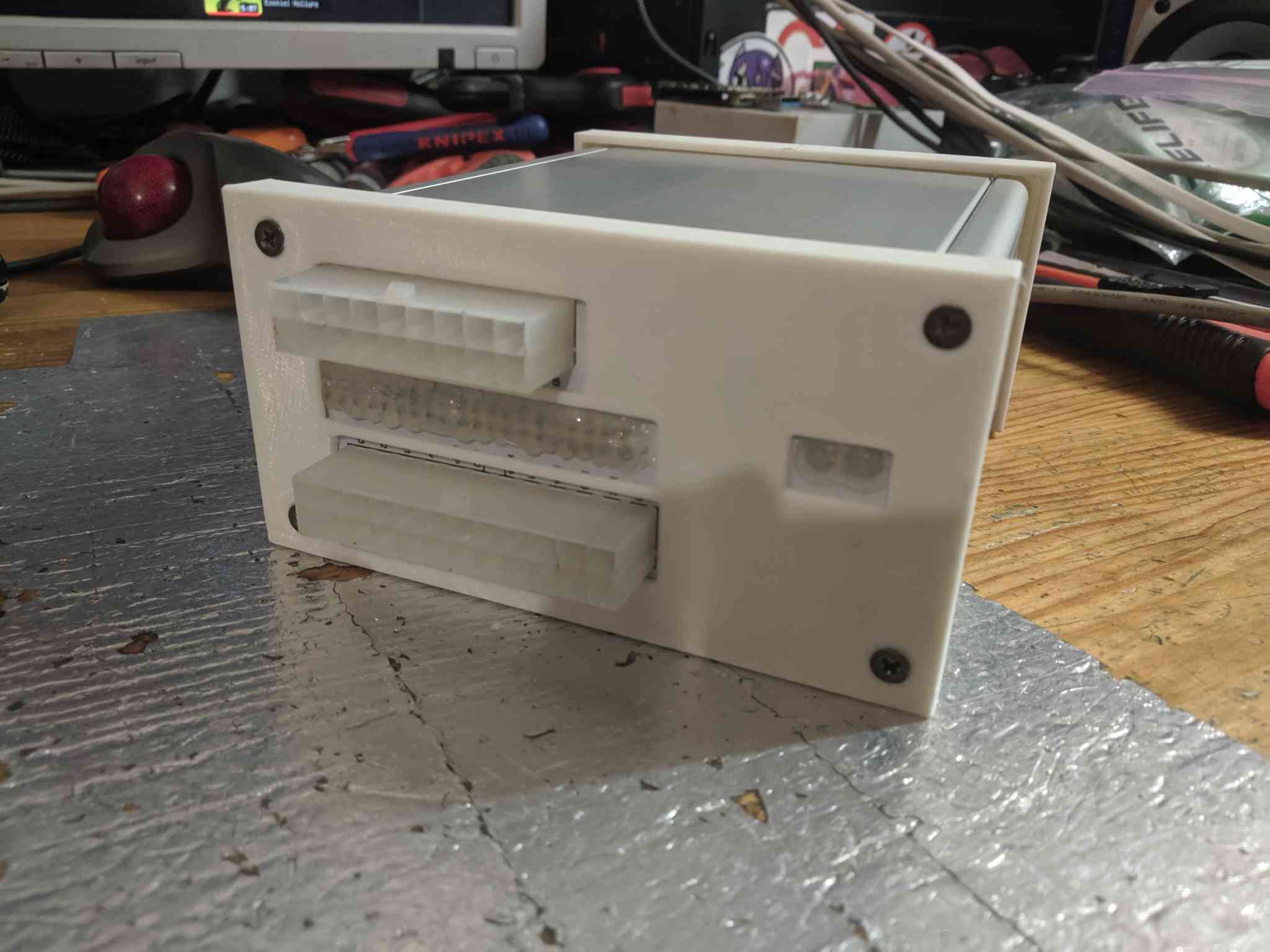
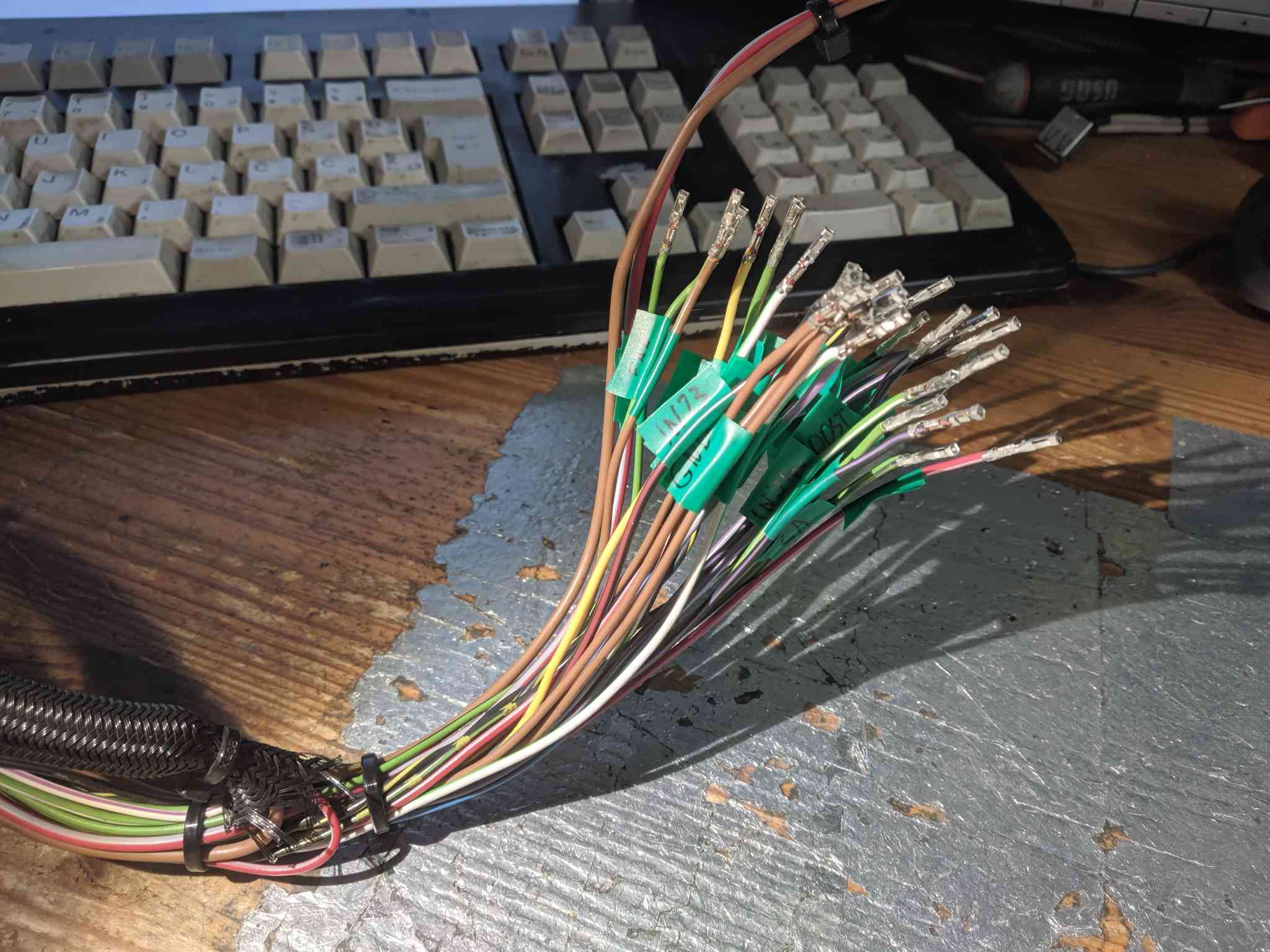
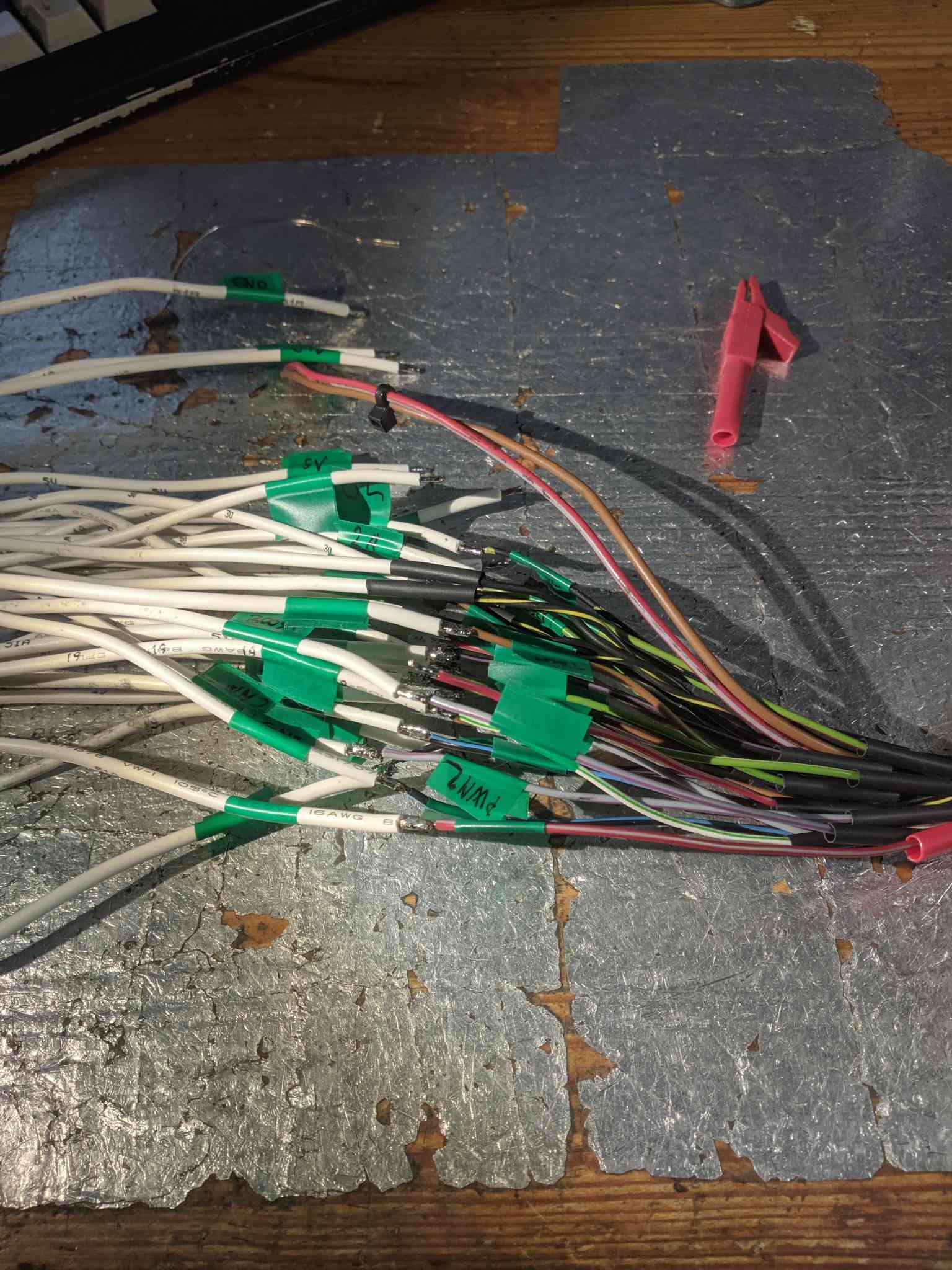
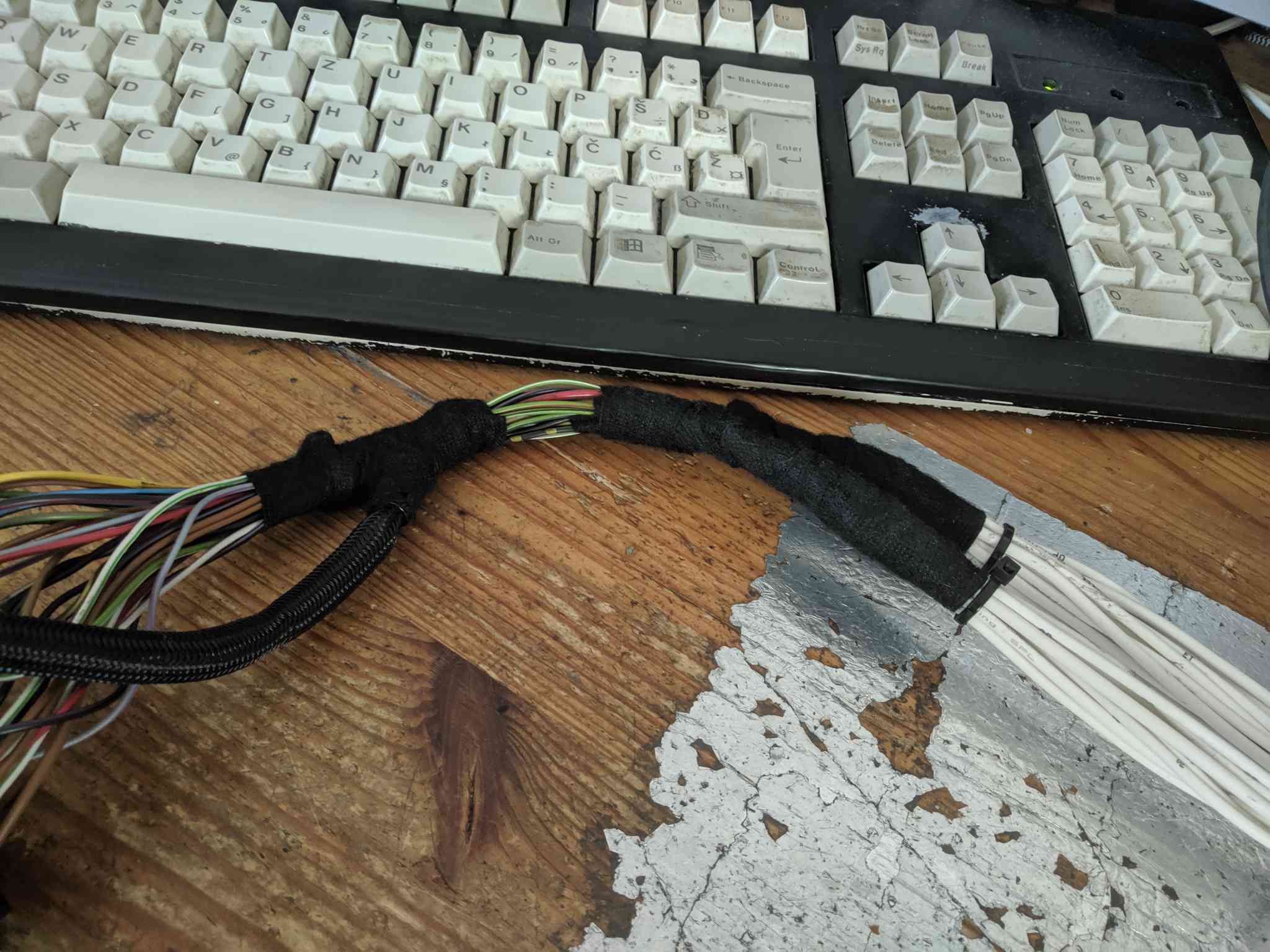
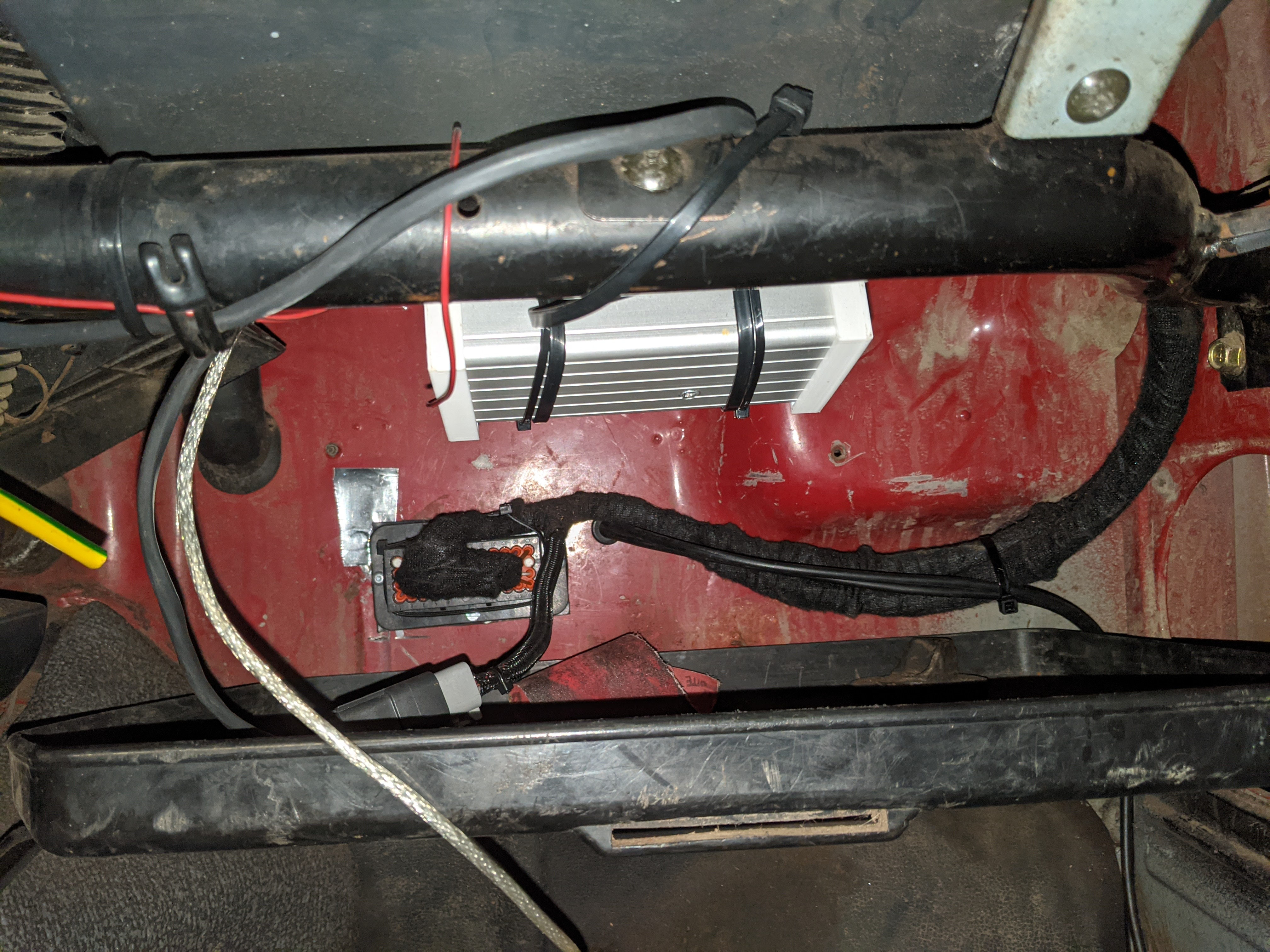
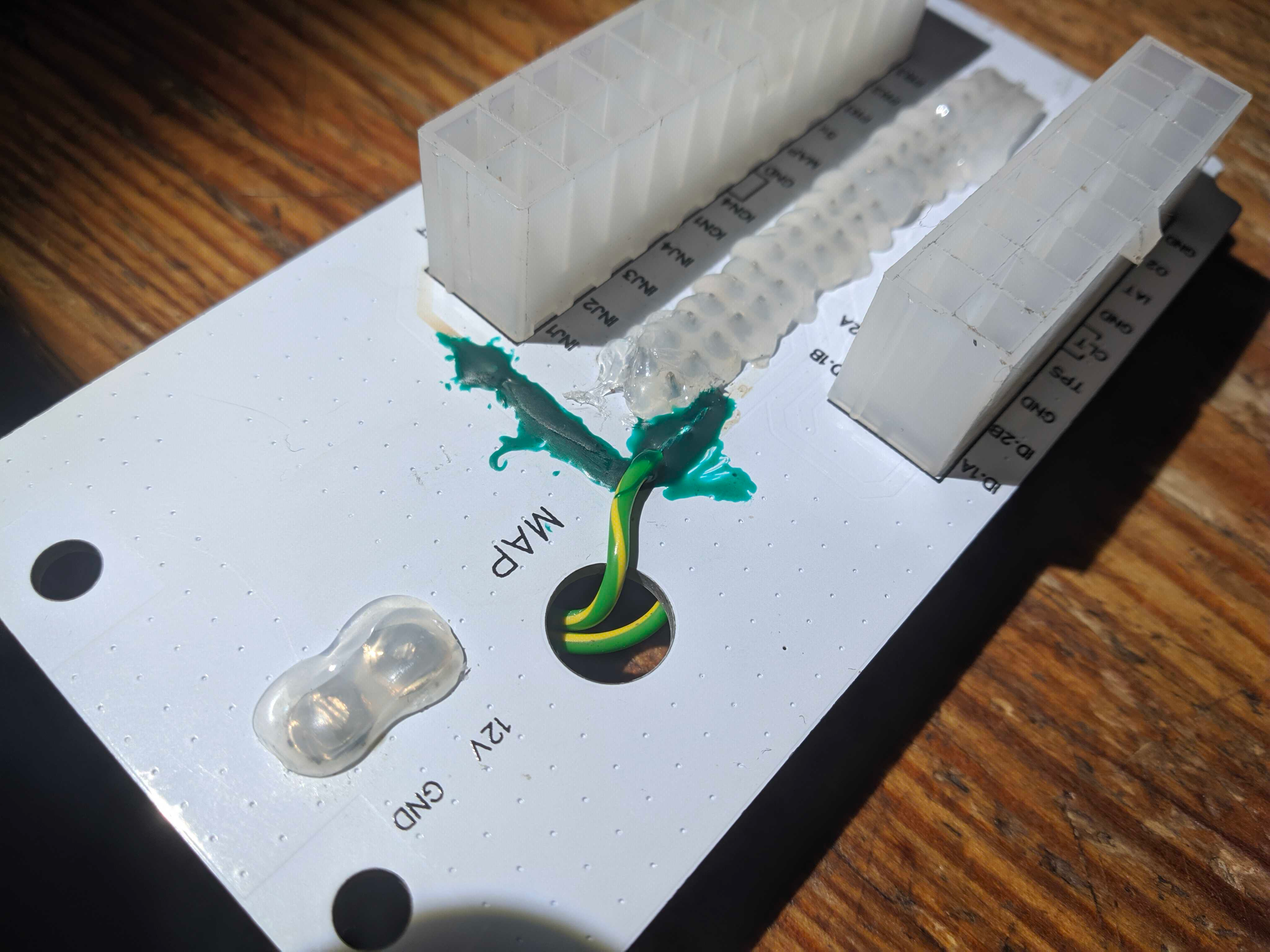
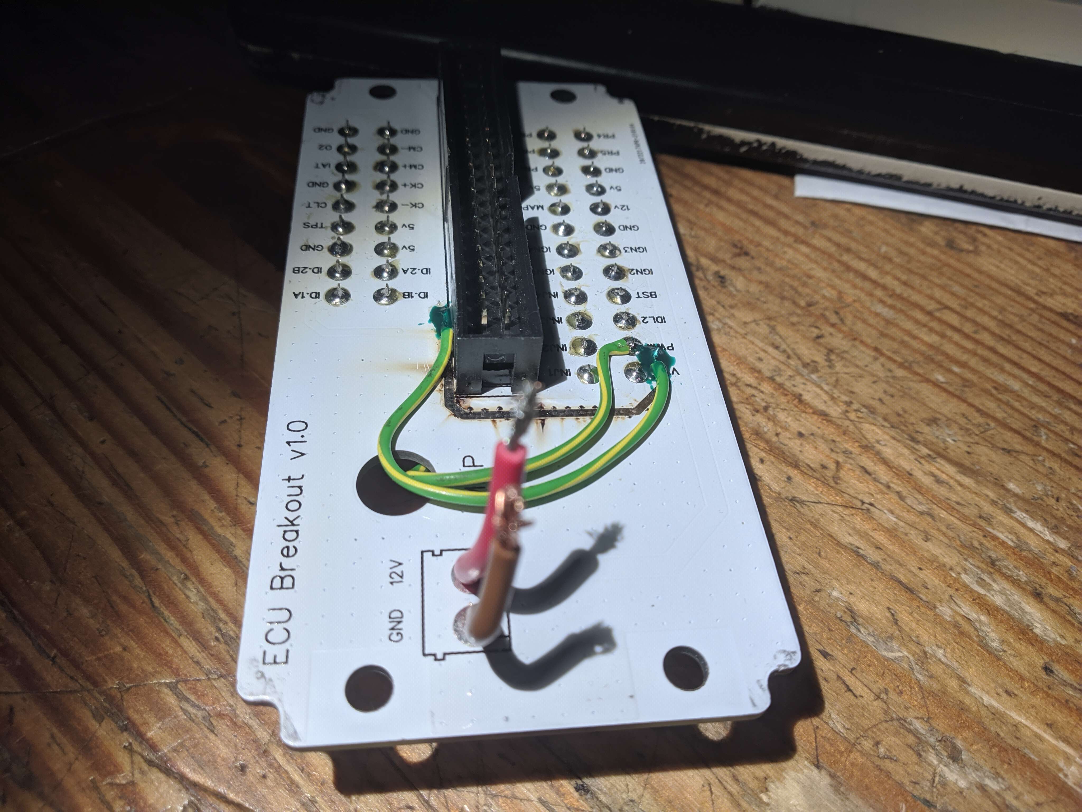
The ECU was originally mounted on a tray under the glovebox and wired into the bulkhead connector in a way that required disassembly for removal.
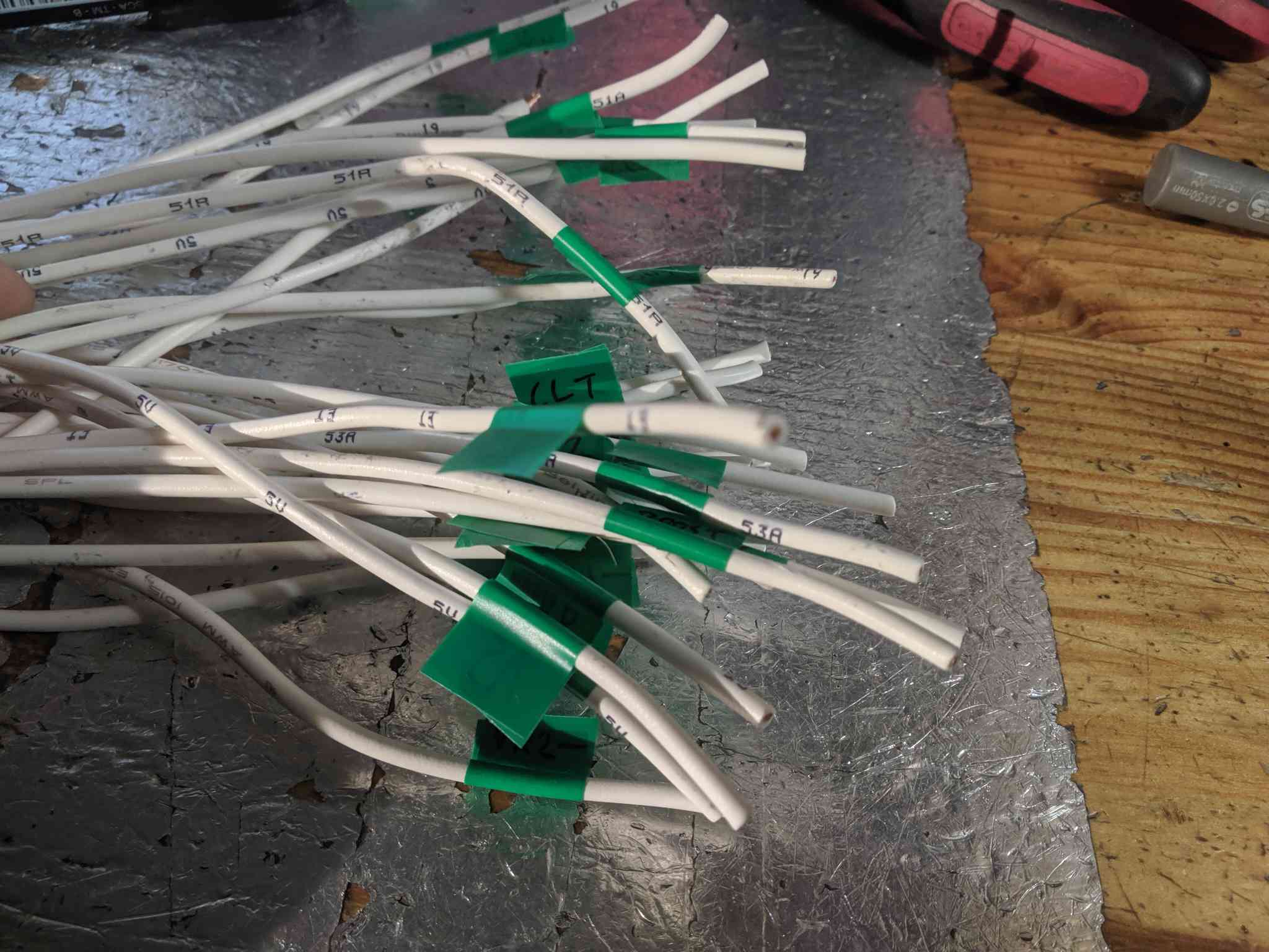
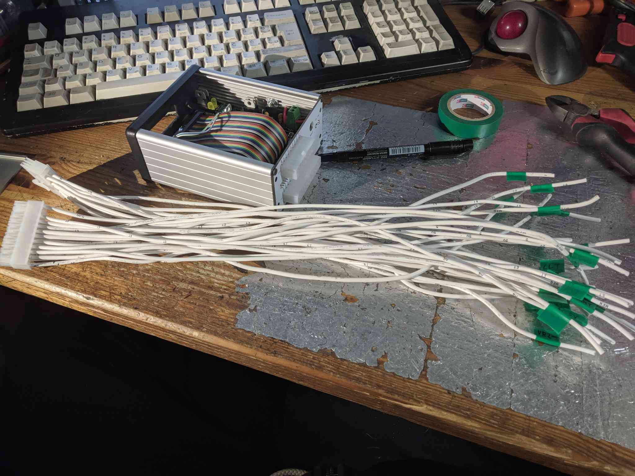
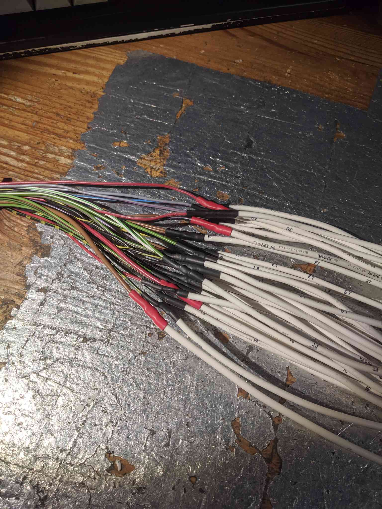
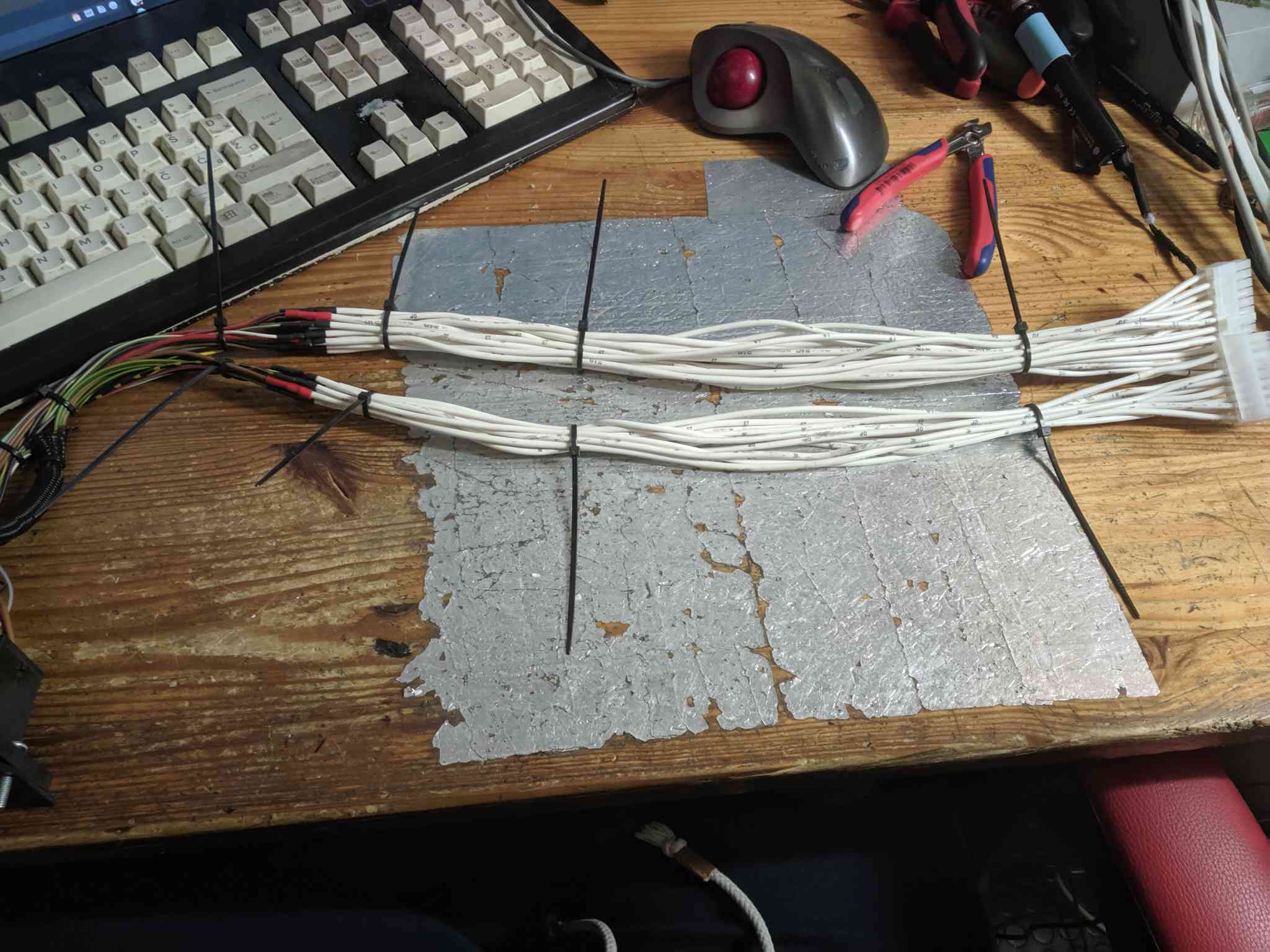
I was able to purchase a faceplate online that had all of the connections broken out into FIT connectors. Now I just had to rewire the interior harness to utilize them.
It was a simple process of cutting, labeling, and splicing. After playing around with the connectors I discovered that the plate wasn't mounted the bed due to being pinched in from the corners
instead of using screw holes. The Hammond case is a C shaped extrusion with a removable 4th wall, this results in warping and the faceplate not staying in.
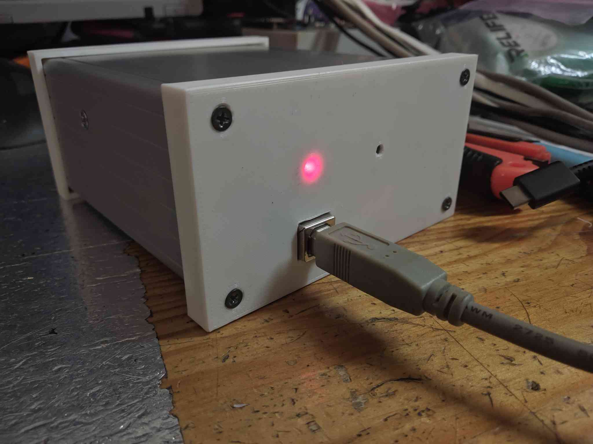
To solve this I designed and 3D printed covers for the faceplate and the other side. I also added an indicator led and a programming button.
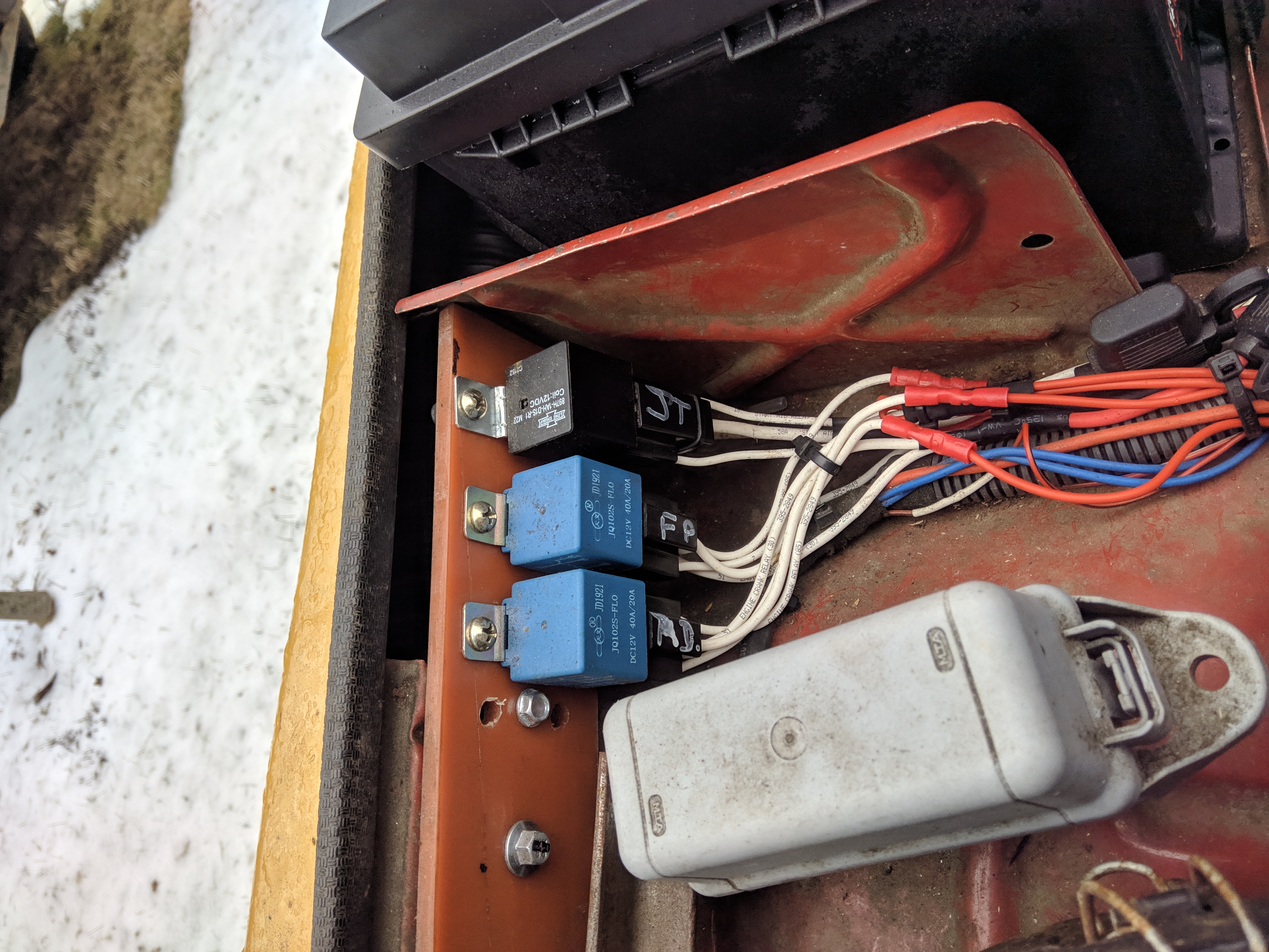
For the ECU mounting I made a small plate that used the glovebox bolt and a pair of zip ties to hold the ECU. There was also a few loose relays in the engine bay which got mounted and labeled.
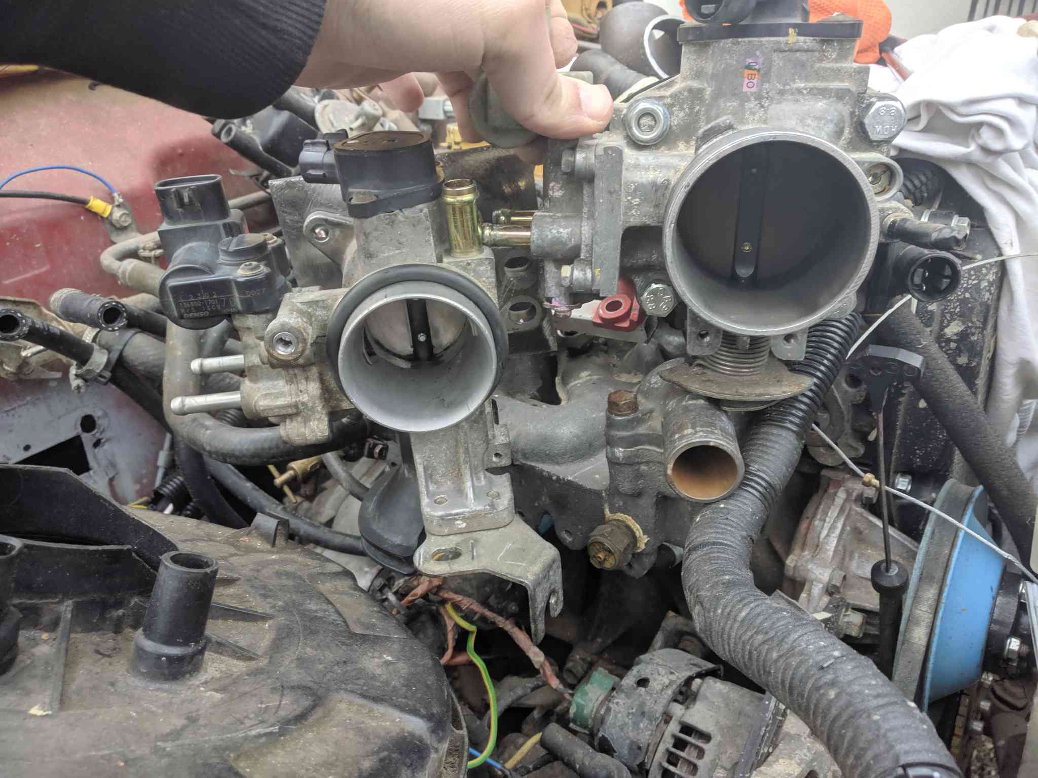
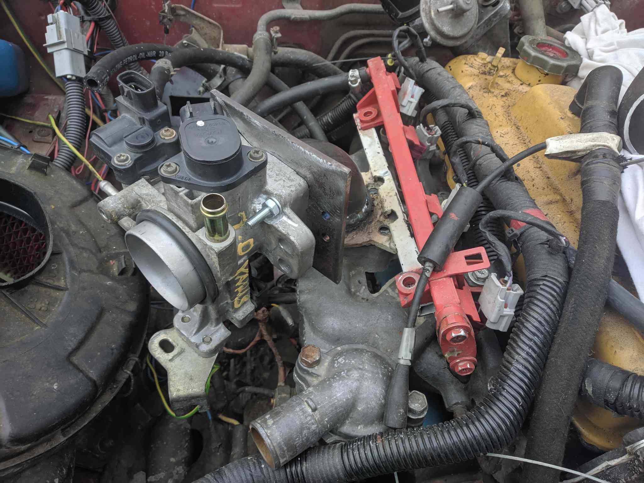
The throttlebody I originally chose was for a Honda D14 66kW and the diameter was way too big. This resulted in poor low throttle granularity and large airflow spikes on transients.
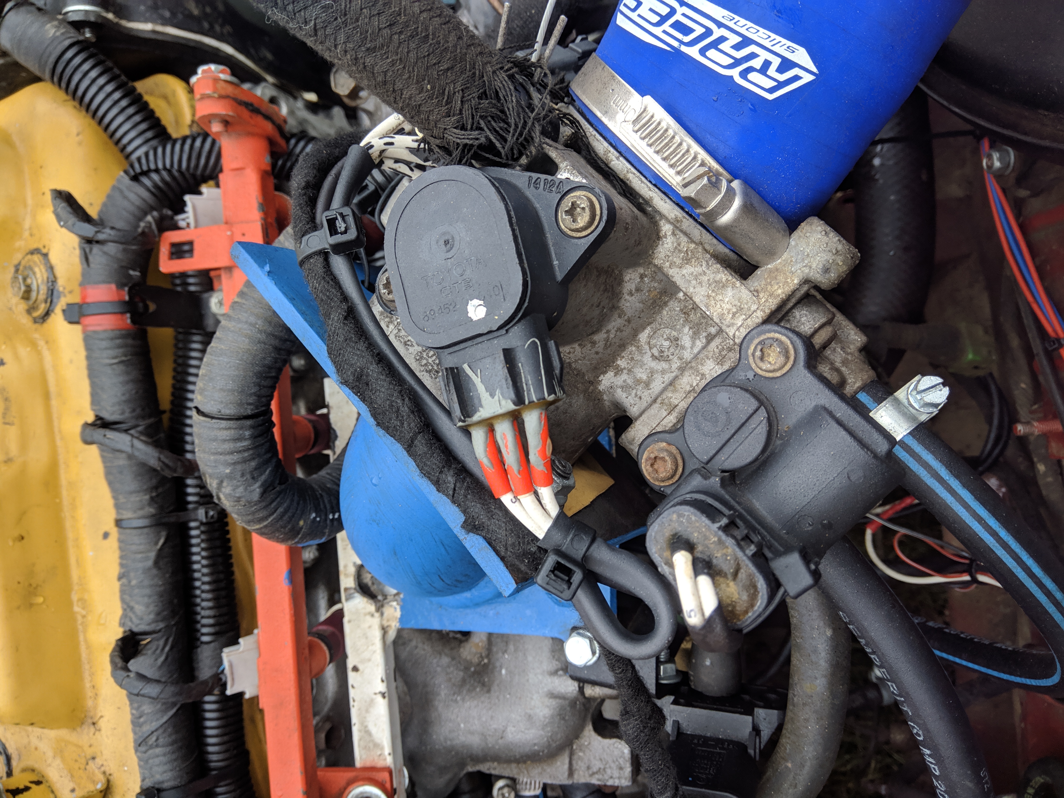
I changed the flange, and had it welded to a 90 degree pipe of appropriate diameter. I was not able to get the right connectors for the TPS and IACV solenoid so I potted wires into them using epoxy and terminated
them with Deutsch DT connectors. I changed the end of the harness for this section to be heatshrunk instead of taped as it is easier to work with in this case. One of the things that changed was the IACV solenoid.
The IACV solenoid on this throttle is from the same Denso rotary solenoid series, but it uses a single coil and a single diode for flyback supression unlike the previous solenoid which used two coils and
bi-directional flyback supressors. The replacement throttlebody is meant for a 50kW 1L Toyota Yaris.
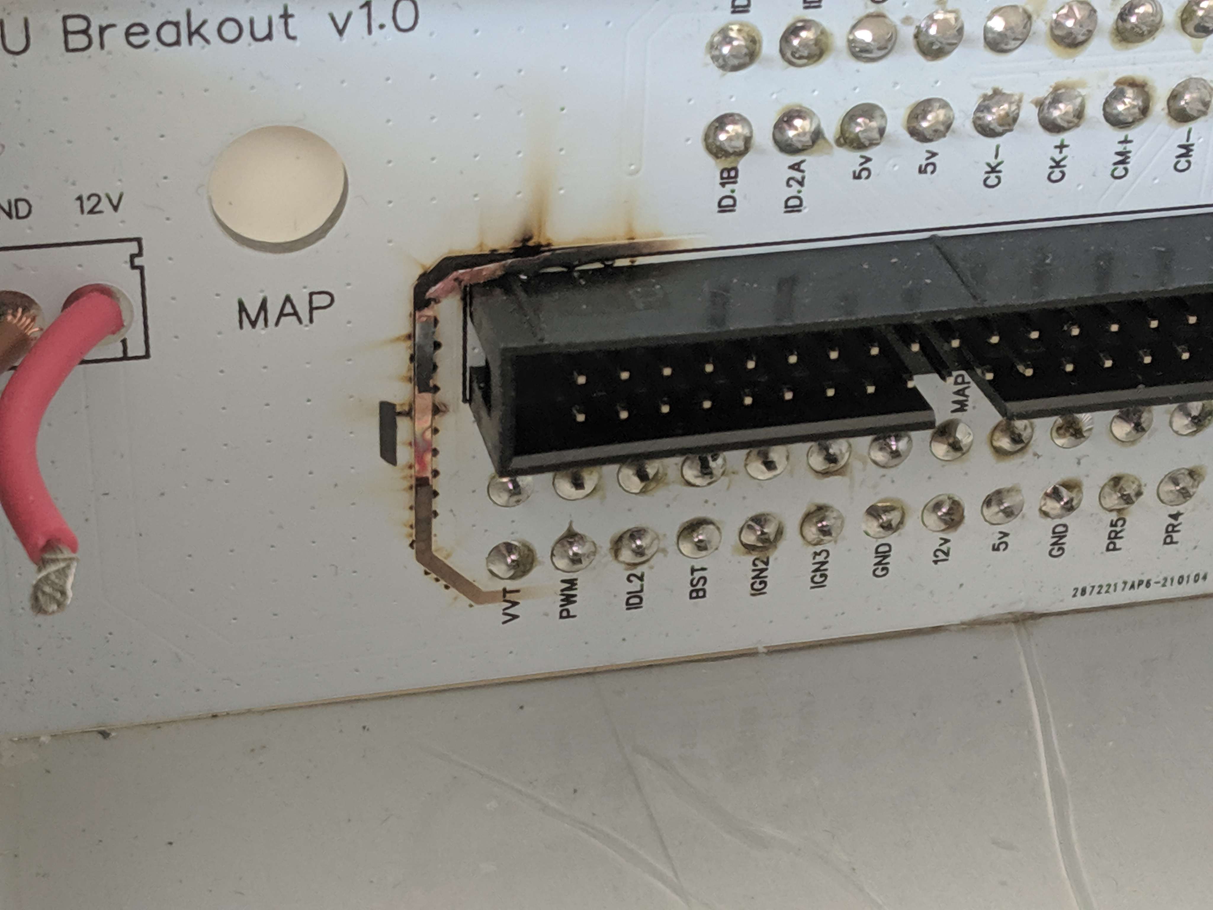
As I mentioned before the new IACV uses a single diode, at first I connected it the wrong way around because I did not check the pinout in the FSM. Result was burnt traces for two of the open drain outputs on the ECU.
I repaired the traces with jumper wires and covered them with conformal coating.
There was a water leak into the driver's side footwell. It came from the windshield frame corner that had rotten out, a degraded seal that soaked the water up contributed as well. The sheet metal required a bit of bodywork, paint, and re-sealing on the DIY hardtop.
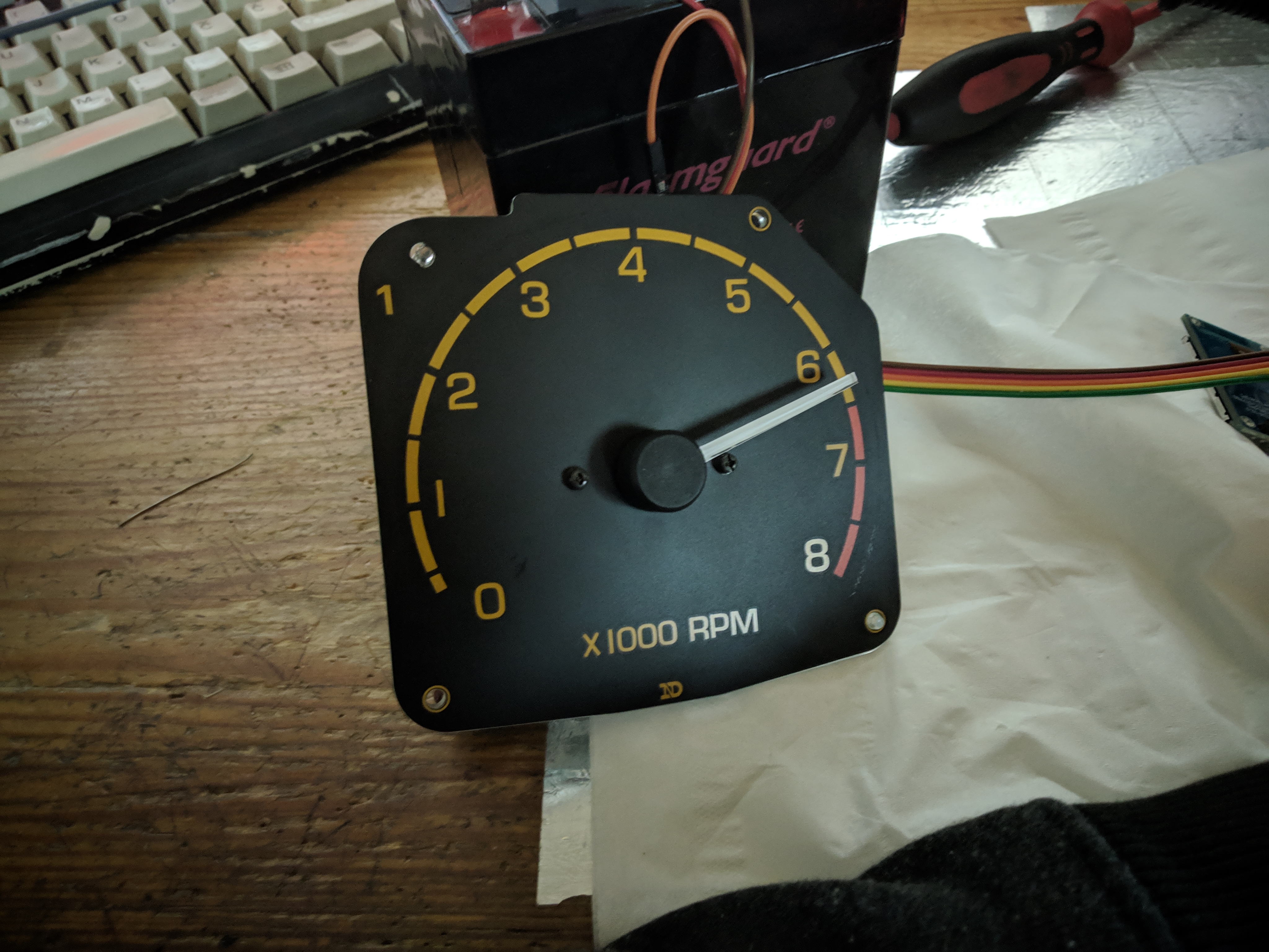
Shortly after the converison I made a temporary cluster made of a fiberglass sheet with a RGB LED, 16x2 LCD and a two digit 7 segment LED display. The LED indicated coolant temperature,
the 7 segment display indicated RPM, and the LCD indicated fuel level, manifold pressure, coolant temperature, AFR, and intake air temperature. Fuel level indication is something that I struggled with for a while,
I saw constant oscillation of the voltage, and it had an offset whenever the fuel pump was active. At first I thought it was fuel slosh from the tank lacking a baffle around the pump, however I later realized that the entire problem
was due to a poor ground at the fuel pump assembly which dropped around .5V when the pump was active, and of course the current draw of a brushed fuel pump oscillates quite a lot and therefore the voltage offset does as well.
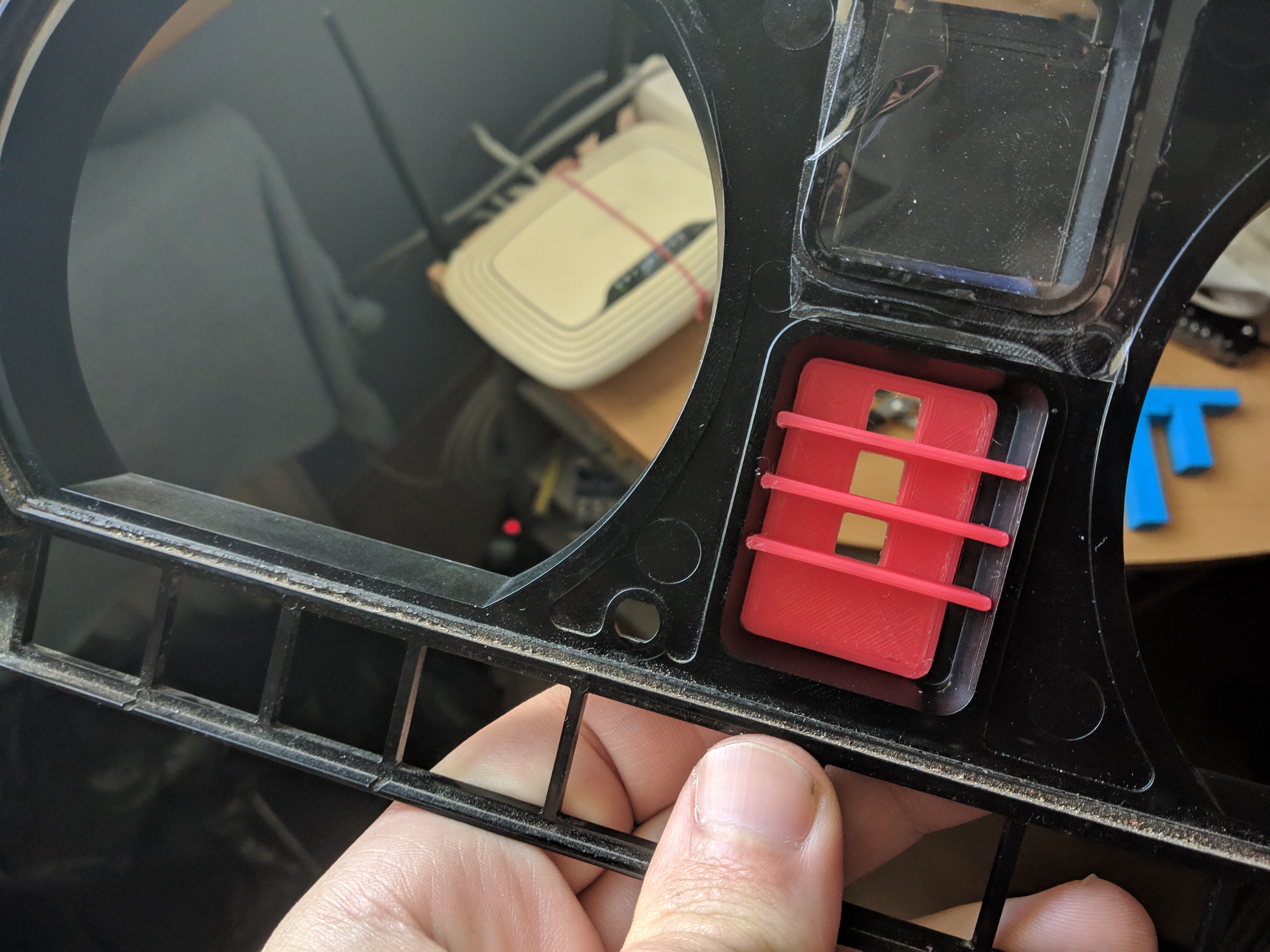
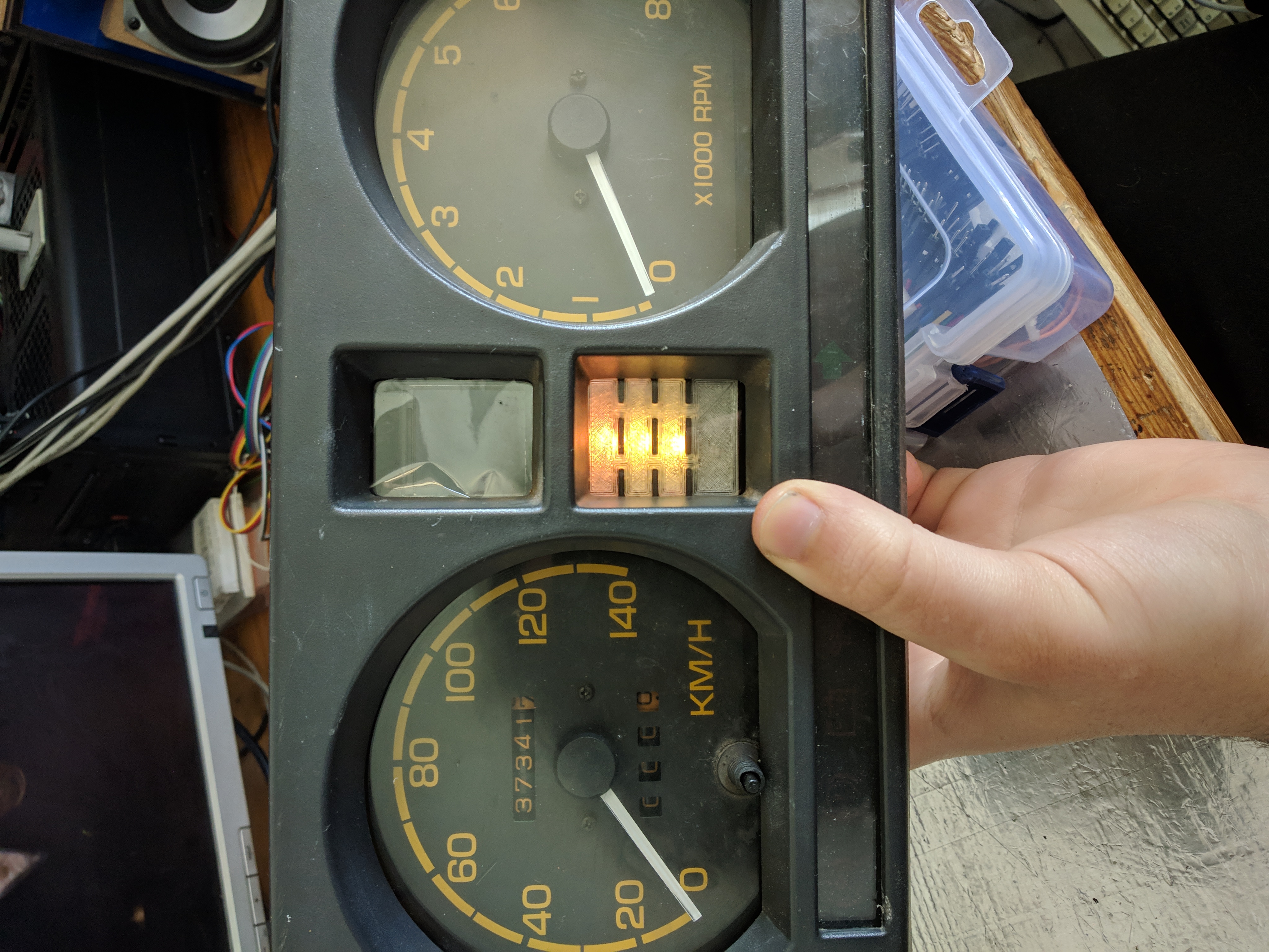
Minor signal instability was still present from (off)road vibration, which was cleaned up with a low pass filter. Final version of the instruments replaces the original coolant temperature and fuel level gauges with a
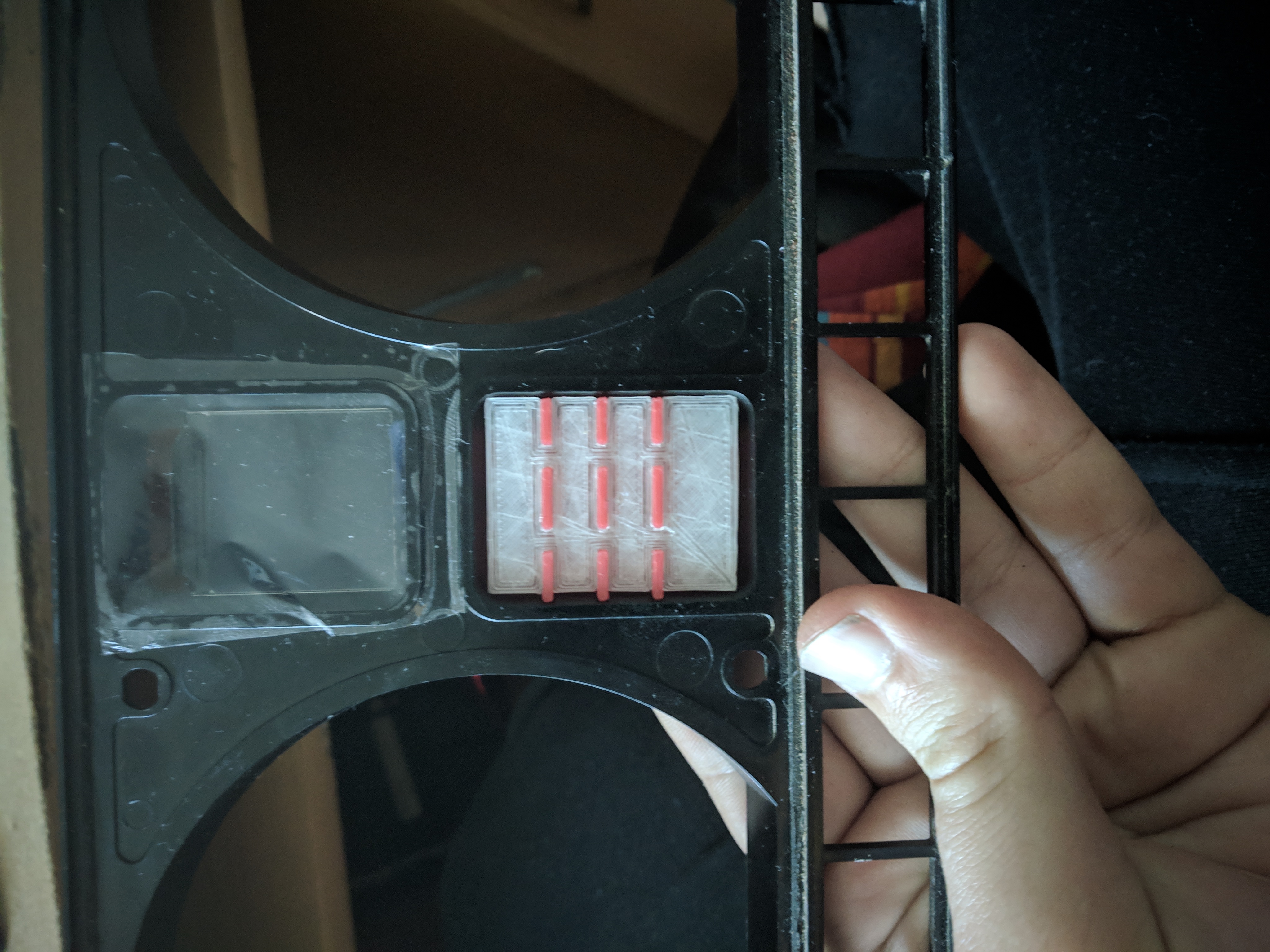
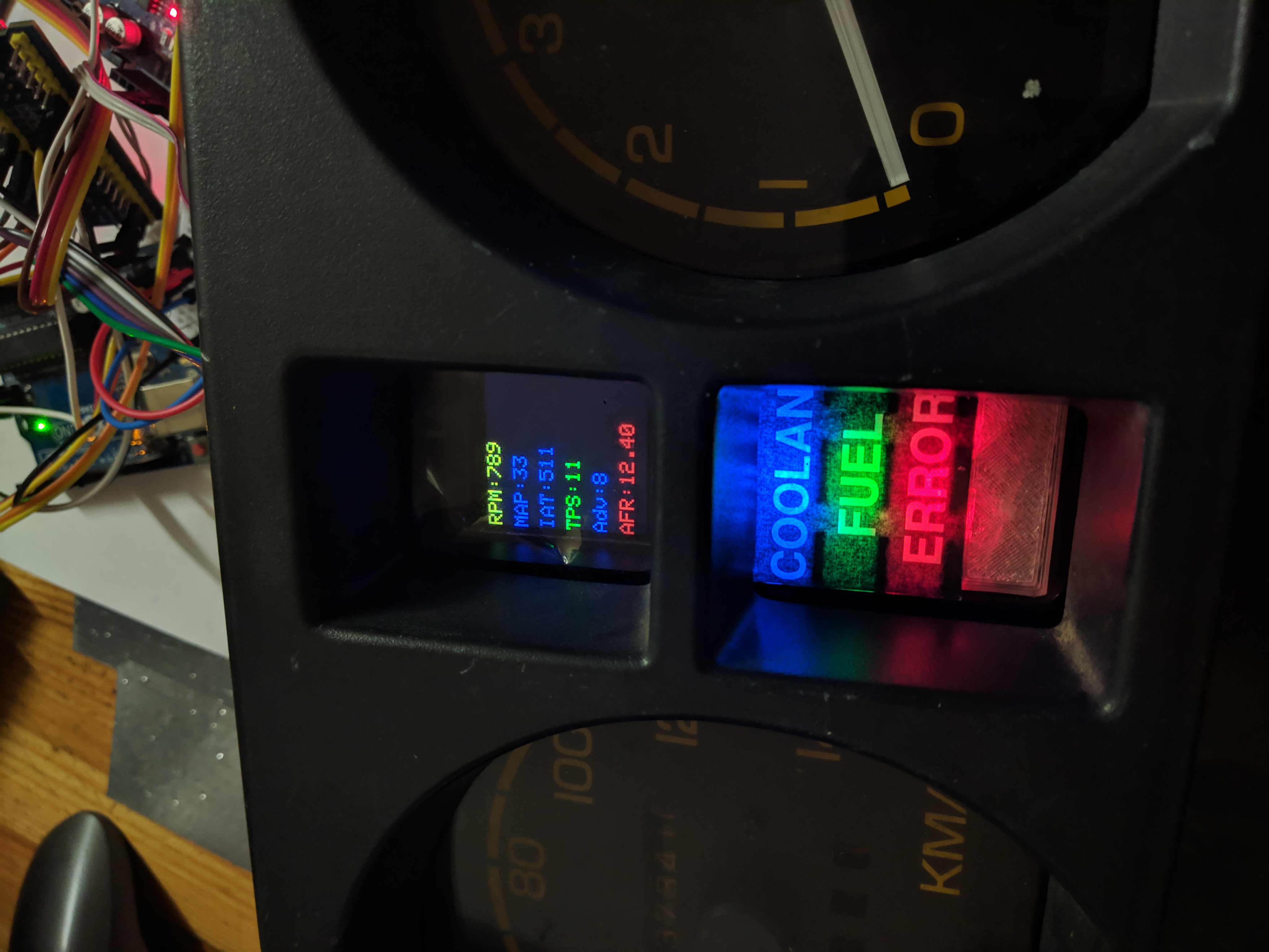
240x240 IPS display and a set of addressable RGB LEDs. The display features two pages, a simple view and an advanced view, they are toggeld with a red button. The simple view shows: Fuel level, Coolant Cold/Nominal/Hot,
Oil Pressure, and Battery voltage. The Advanced view shows RPM, MAP, IAT, CLT, AFR, TPS, Battery voltage, and Fuel level. There are 4 LEDs located under the LCD, 3 are addressable RGB LEDs. They indicate:
Coolant temperature, Fuel level, Dashboard Errors, and Fuel pump on/off status. The fuel pump is on a manual switch. Error LED lights up for malfunctions such as Oil pressure sensor disconnected
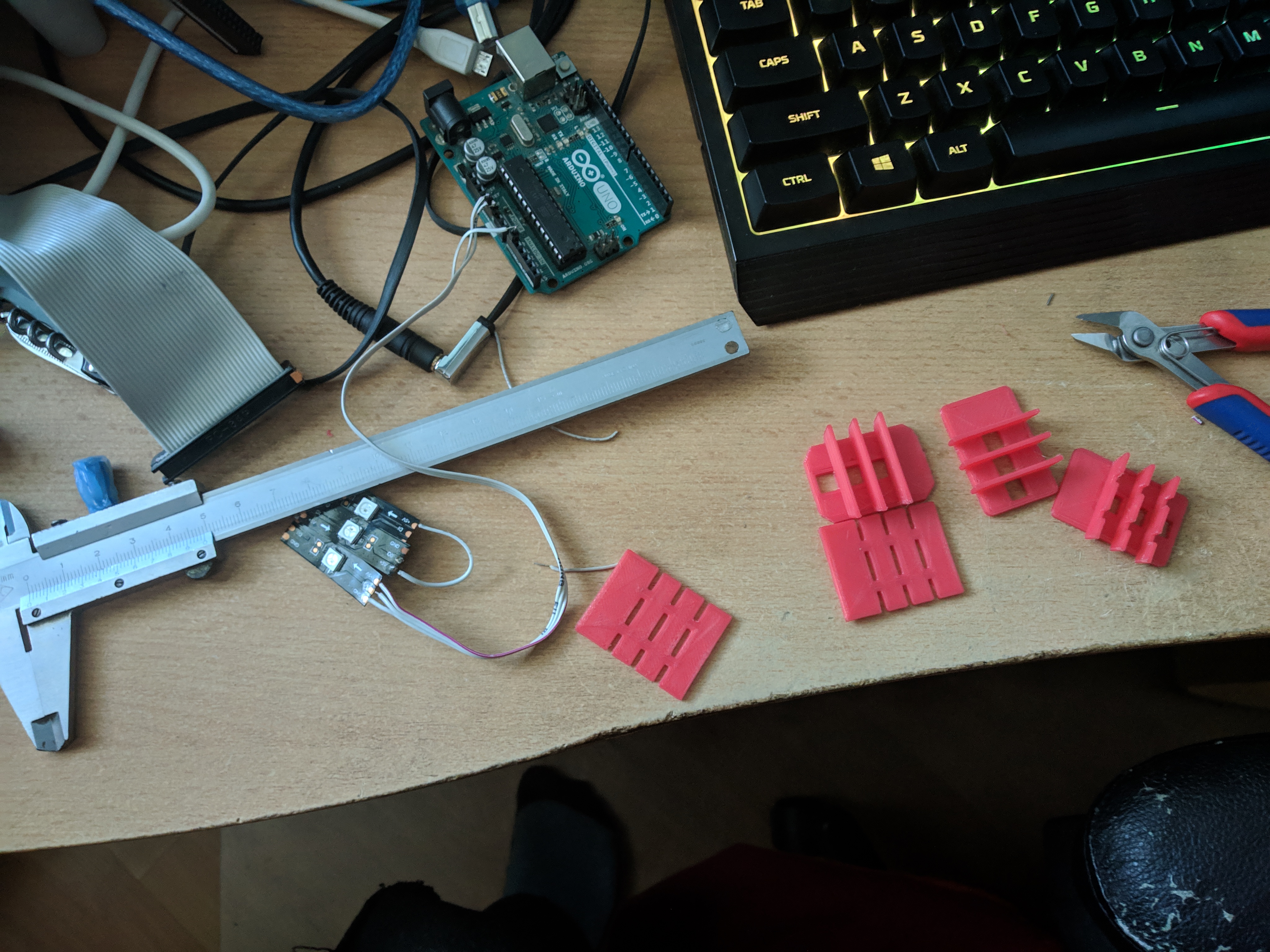
or the Serial connection to the ECU not working. The LEDs are mounted in a 3D printed frame with a 3D printed diffuser.
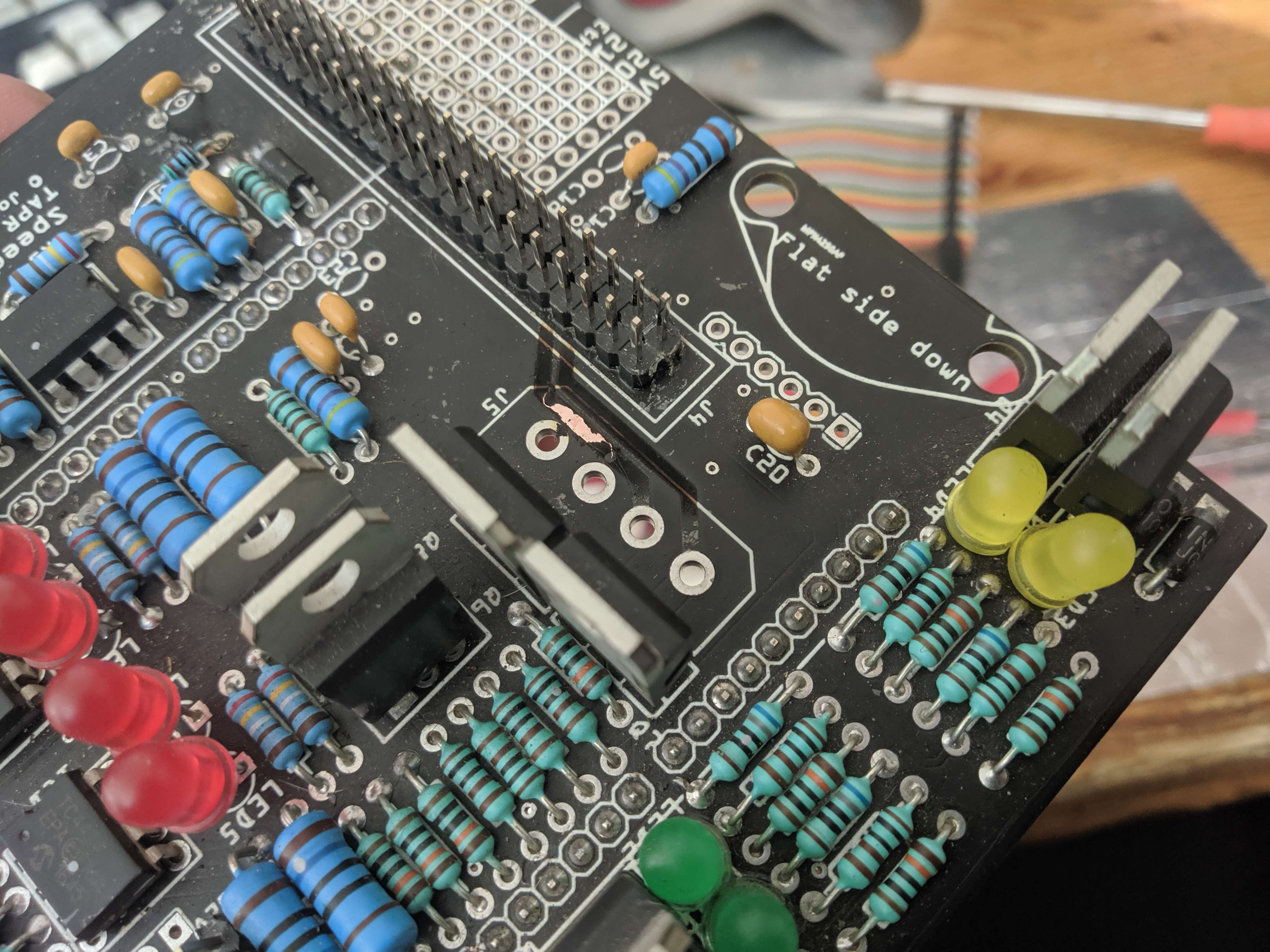
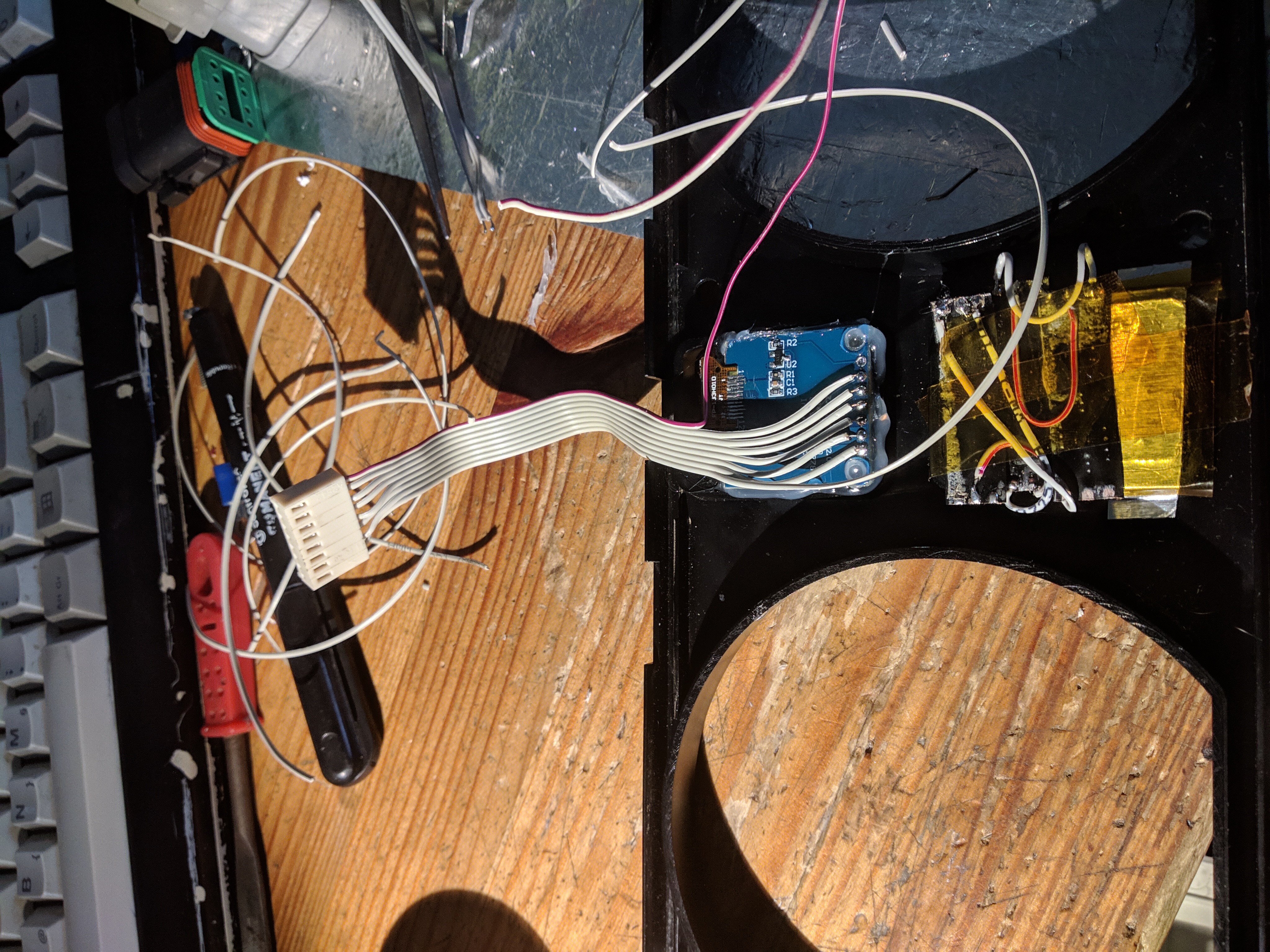
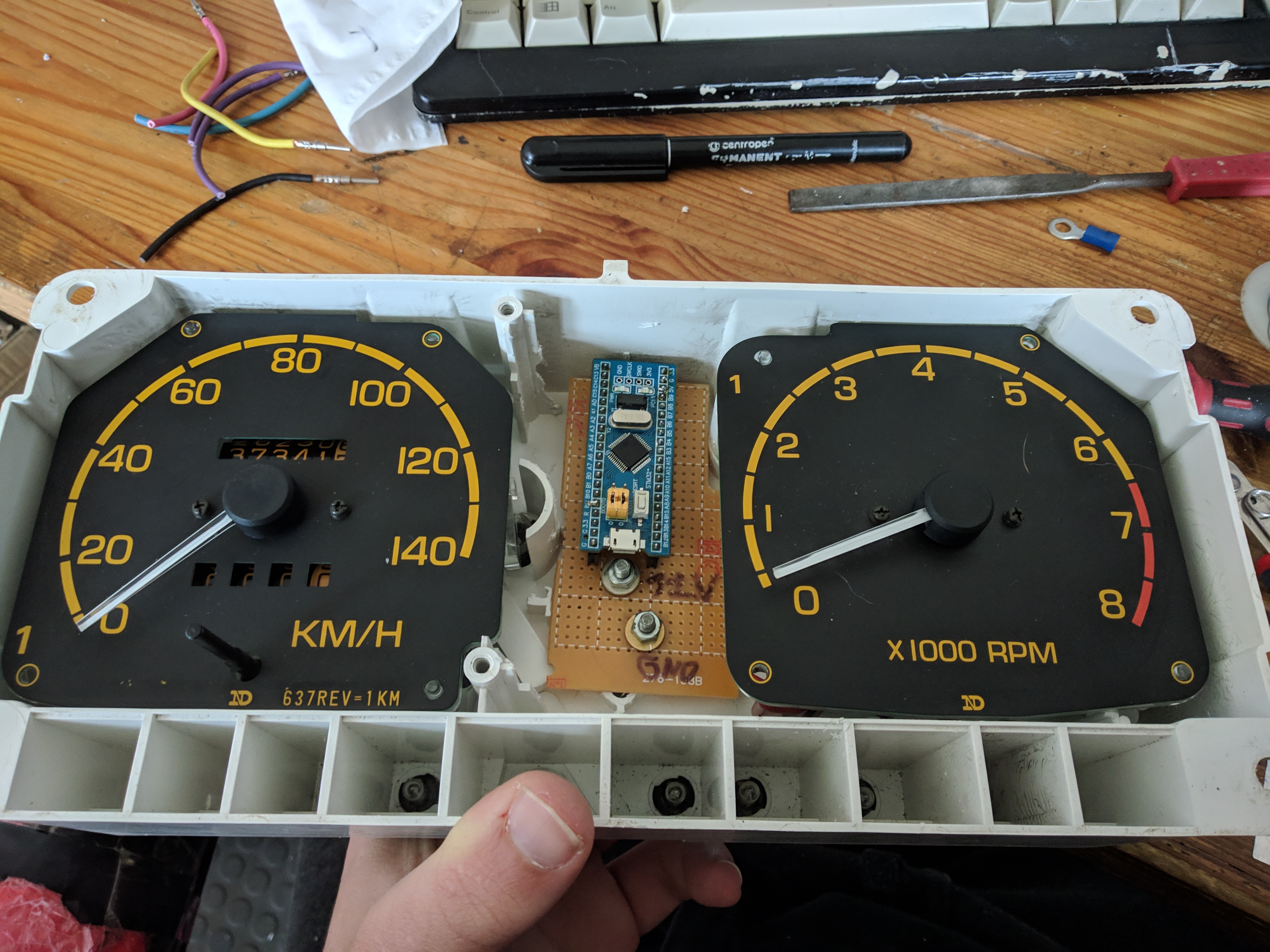
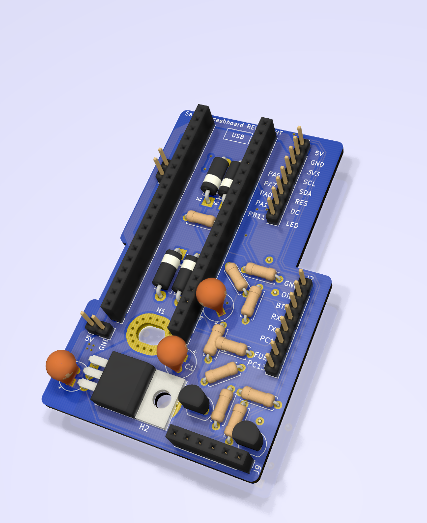
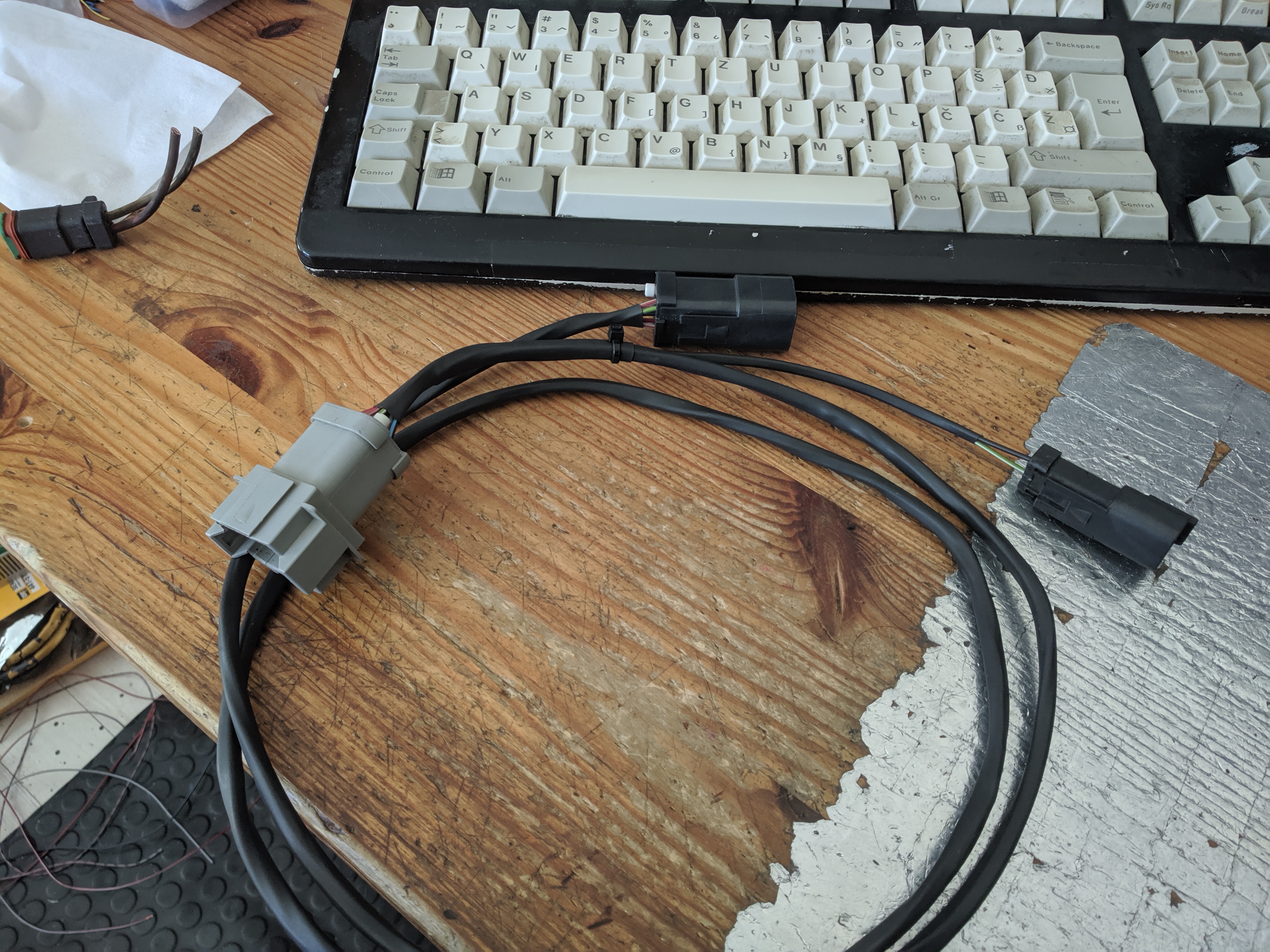
This cluster is powered by a STM32F103 development board on a PCB that I designed, it connects to the ECU and chassis wiring with a short harness
that is heatshrunk and terminated with Deutsch DT connectors. First testing was done with a hand built circuit board, but later on I replaced it with a manufactured piece. I had issues with the LCD going out
randomly, this turned out to be a poor factory solder joint between the flat flex and carrier PCB. Ribbon cable between the front piece and the internals was also changed multiple times to allow for easier service.
I utilized a 5V square wave output on the ECU for the tachometer which originally used the flyback spike of the ignition coil. It works as a frequency counter and I only needed to change the input voltage divider.
Page viewed best on a UXGA monitor in Firefox with Terminus font and a dark background