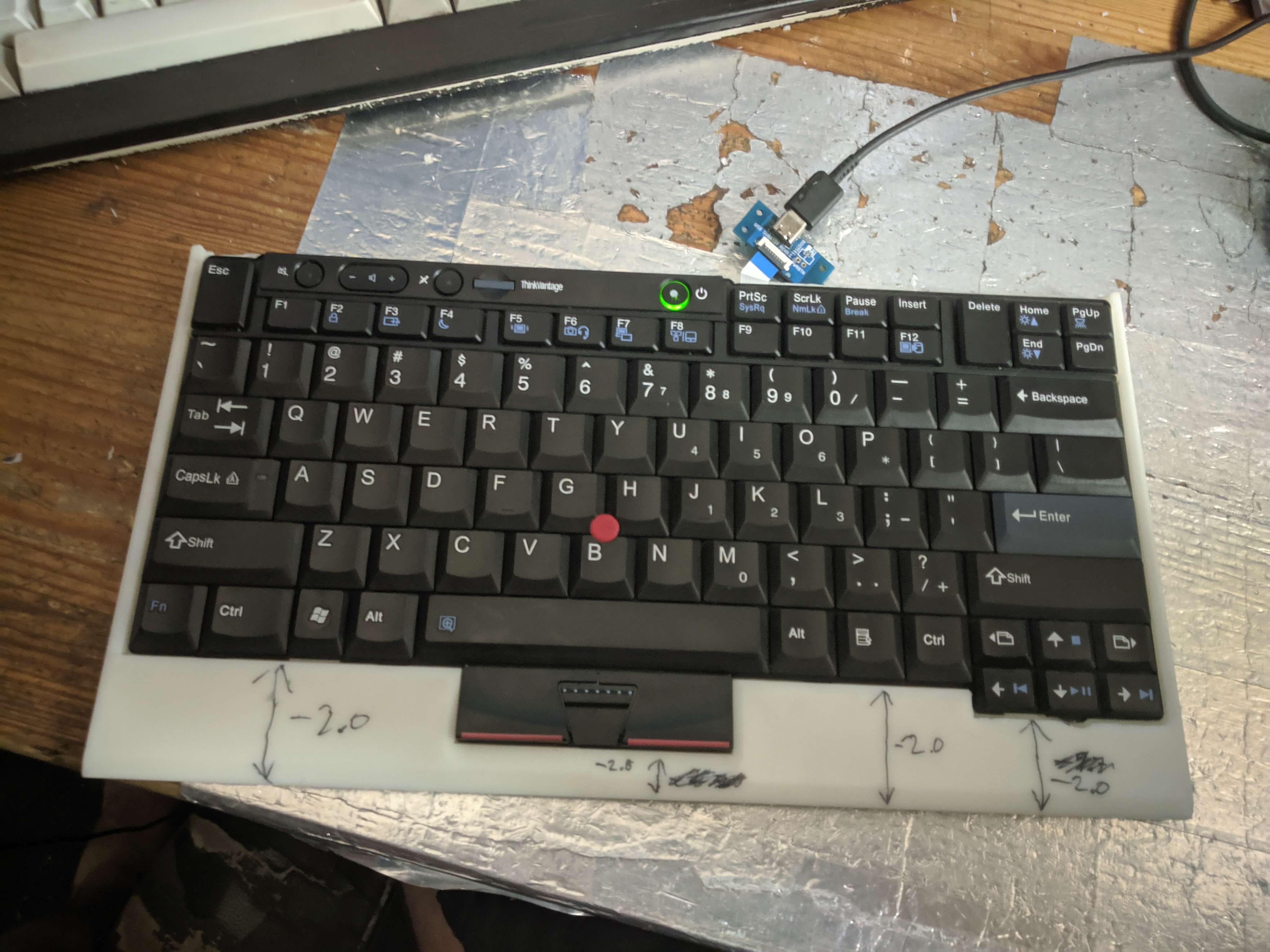
I love the ThinkPad 7 row keyboard, In my opinion it's one of the best small form factor keyboards out there, and I would like to use it on my desktop PC.
Luckily Lenovo has the SK8855, SK8845, and SK8835, sadly the SK8855 is long term unavailable, and when they pop up on the used market their prices are unreasonably high.
The latter SK8845, and SK8835 are low cost server accessories and they don't feel good to type on. A while ago I have tried using an STM32F103 bluepill board to create a controlller
however it didn't perform the way I wanted and so I abandoned the project, at the time it was with a T40 keyboard. With at the time newly released RP2040 the opportunity
to make this project work came along.
Key points of this project are:
a 7 row keyboard controller
Run QMK on it
Create a usable desktop keyboard
Utilized extra keys such as the power button
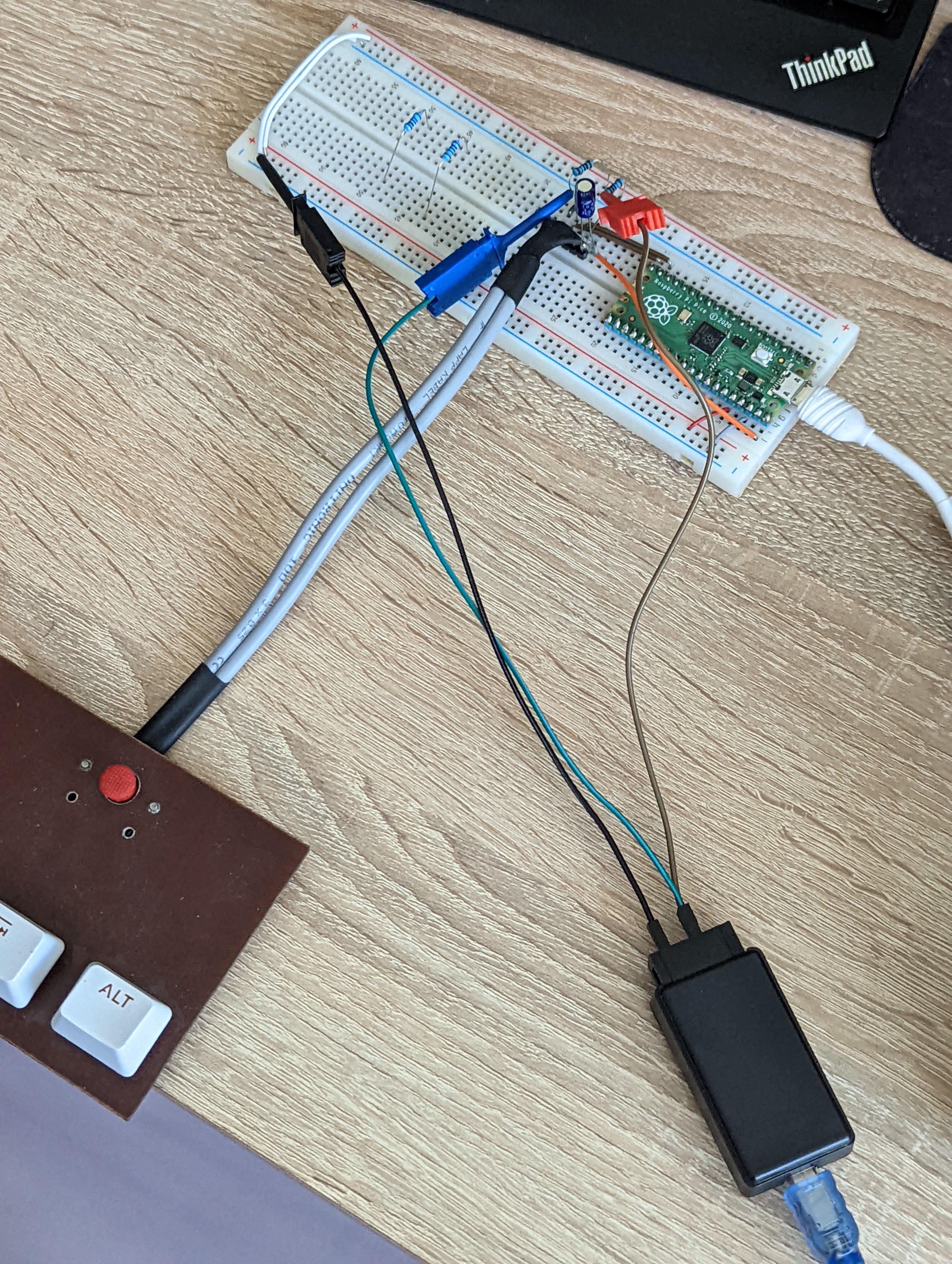
First things first, a proof of concept is in order, at the time when we started this project the freshly released RP2040 had QMK support, but no trackpoint support.
I started off by making a trackpoint carrier that could easily be hooked up to a Pi Pico and debugged. My friend Gamiee took care of the PS/2 driver via PIO.
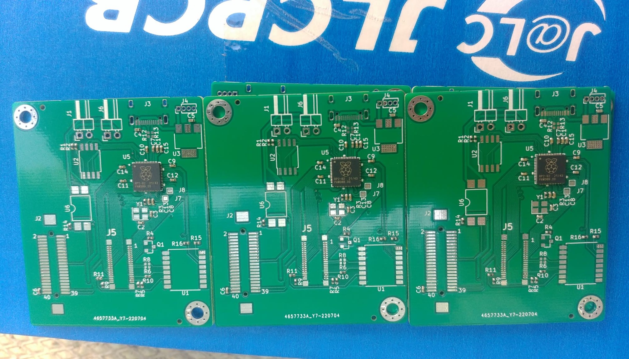
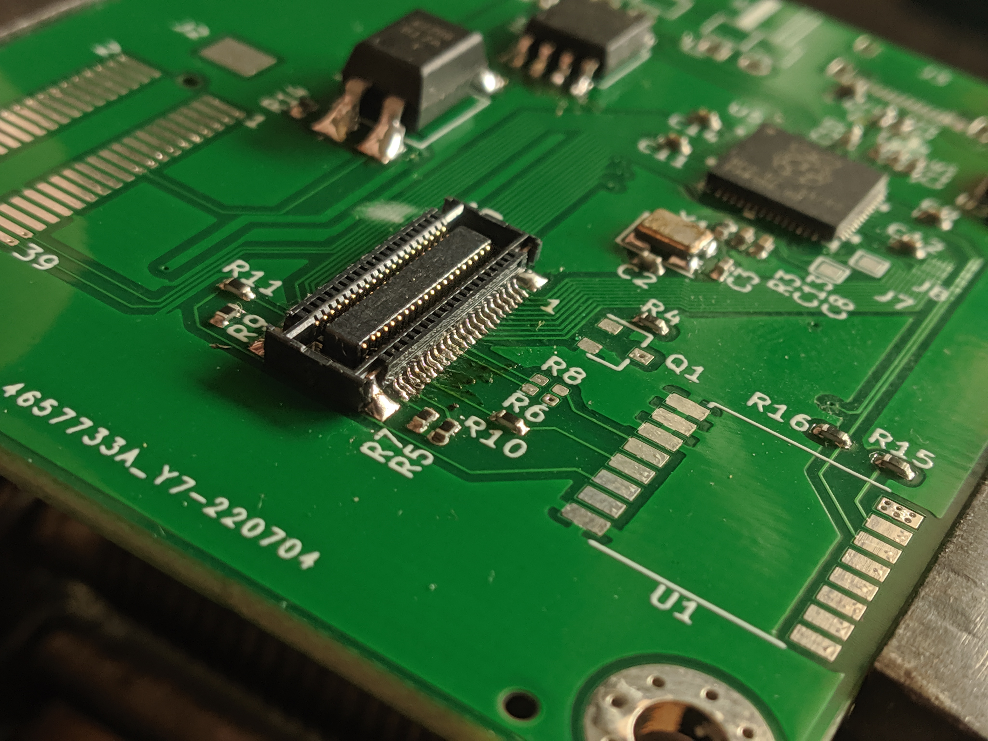
After we had a functional PS/2 driver for the RP2040, I designed a test board for the whole keyboard to be hooked up. The entire IO of the RP2040 is utilized
for the keyboard matrix other than two pins which we used for an IO expander, this IO expander takes care of the LEDs. Sadly it is not viable to use it for extra keys like the power button
because it's interrupt pin couldn't be hooked up to the RP2040. This initial revision supports T4x series, keyboards, and from T60 to T430. During the design I overlooked connector orientation
so the USB-C connector ended up facing the user. JLCPCB's pcb assembly service was used to populate majority of the 0402 passives, and the MCU. This revision utilized
a supposedly compatible replacement connector for the keyboard, however it turned out to be quite far from plug and play and permanently damaged the keyboard's connector by breaking it's key.
By this point I have a rough idea of what I want to do, how to mount the board into a case, and how to make the USB connector durable.
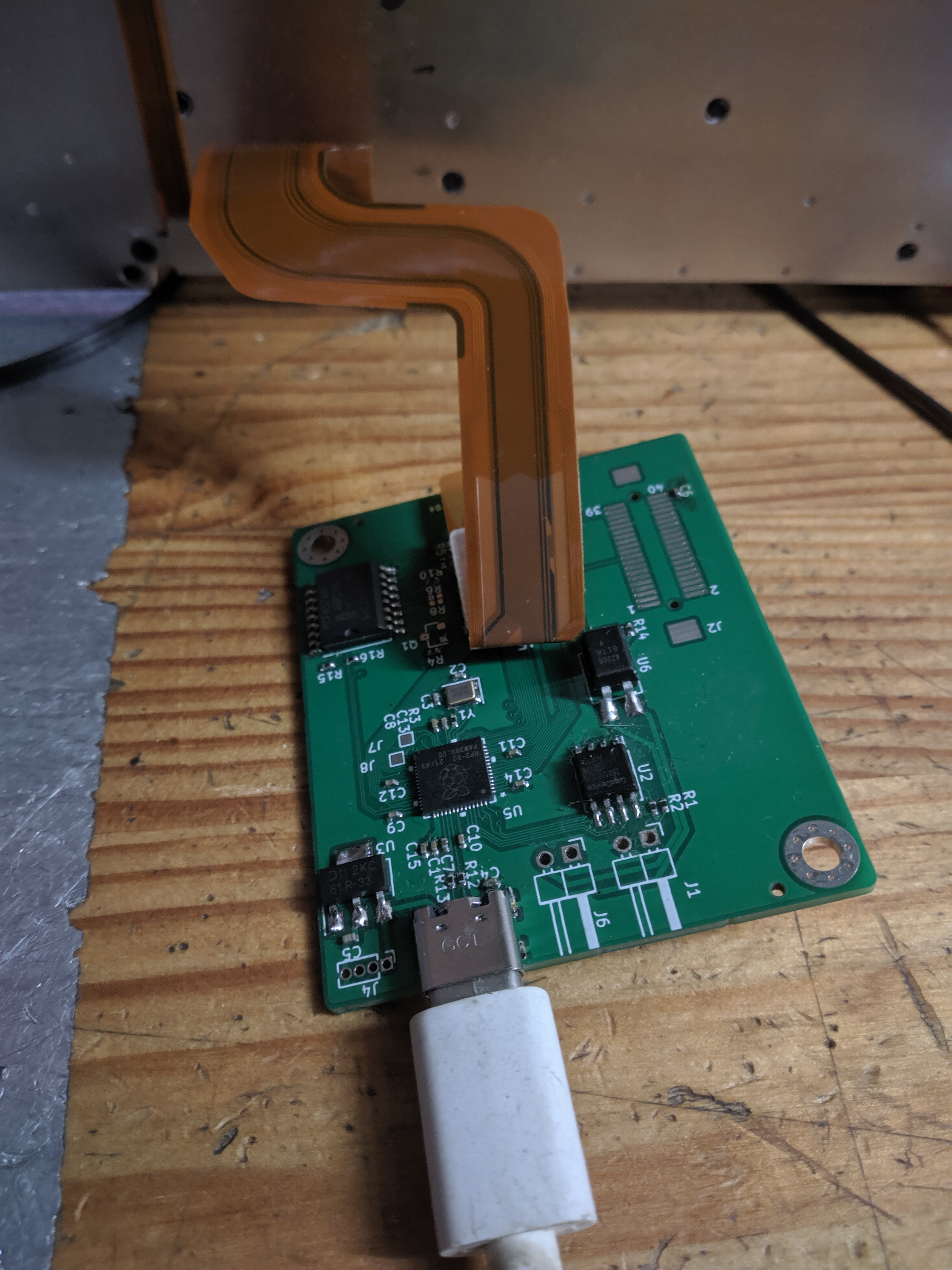
Most significant change here is the use of the original connector that we managed to source, and a board shape that tucks in around the keyboard. The USB is on a subcard connected via FPC.
JLCPCB Assembly was yet again utilized, other than the connectors, the BOM remained unchanged including with some very bulky parts. This time I also took the effort to length match the USB differential pair.
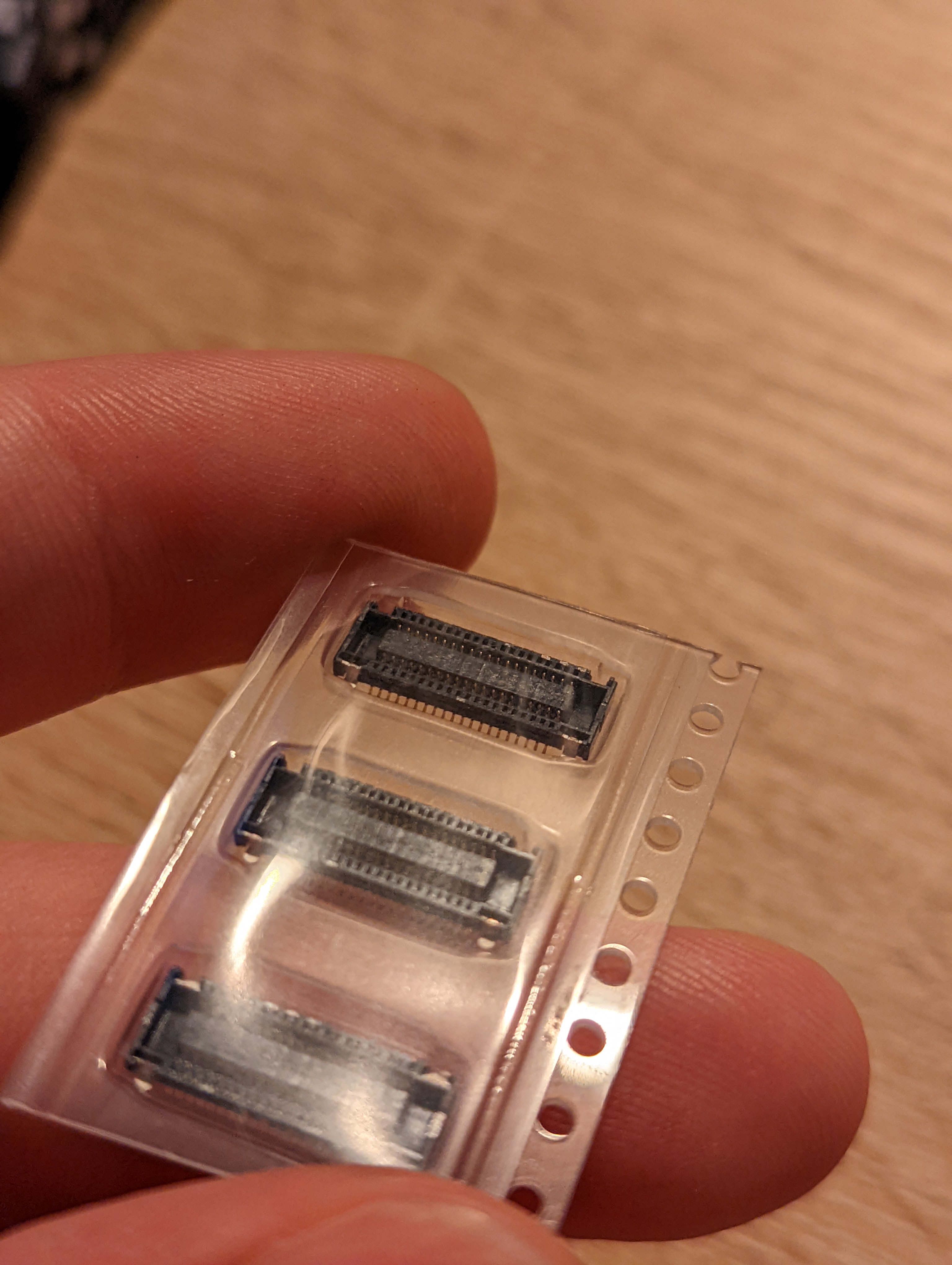
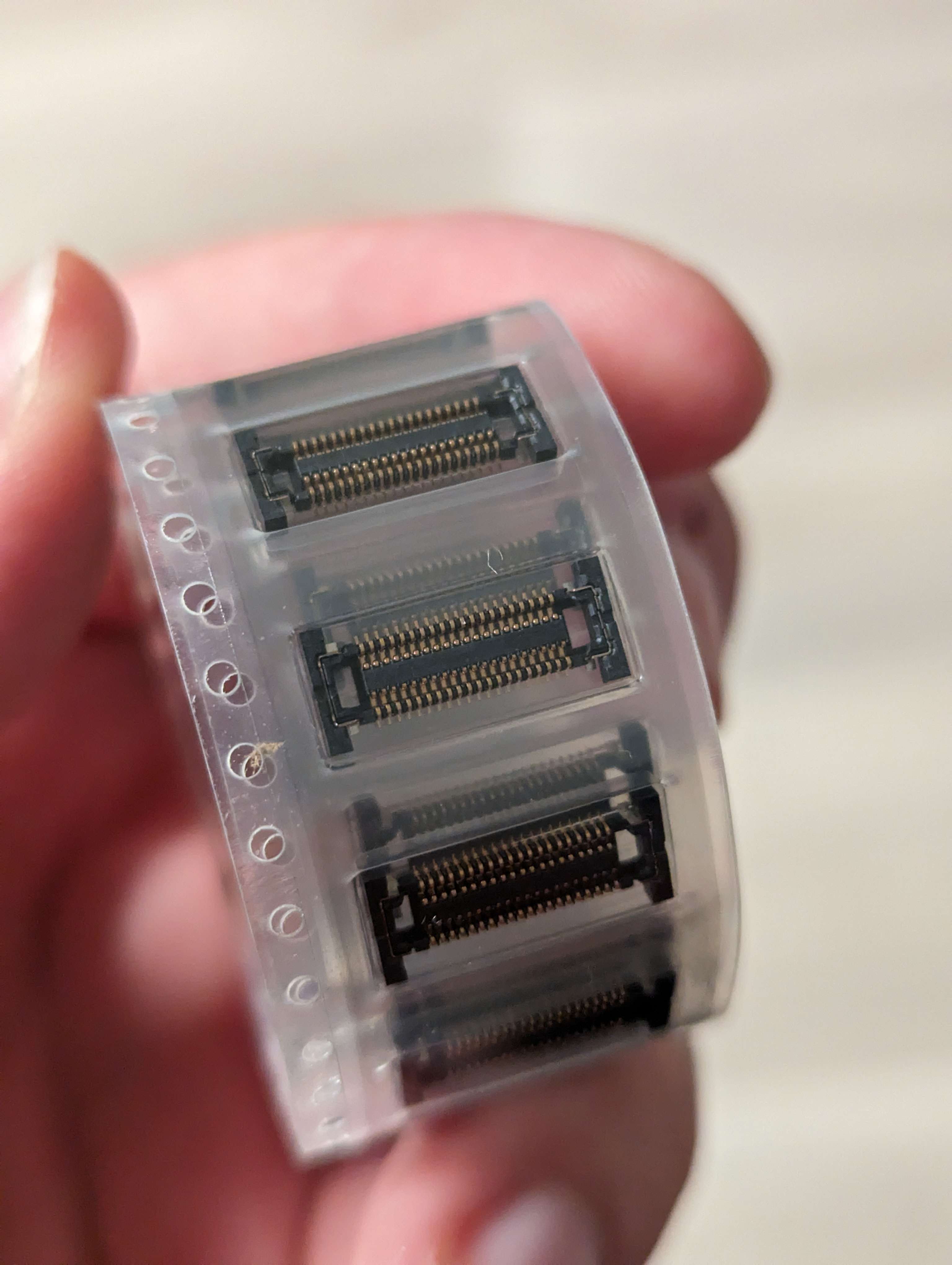
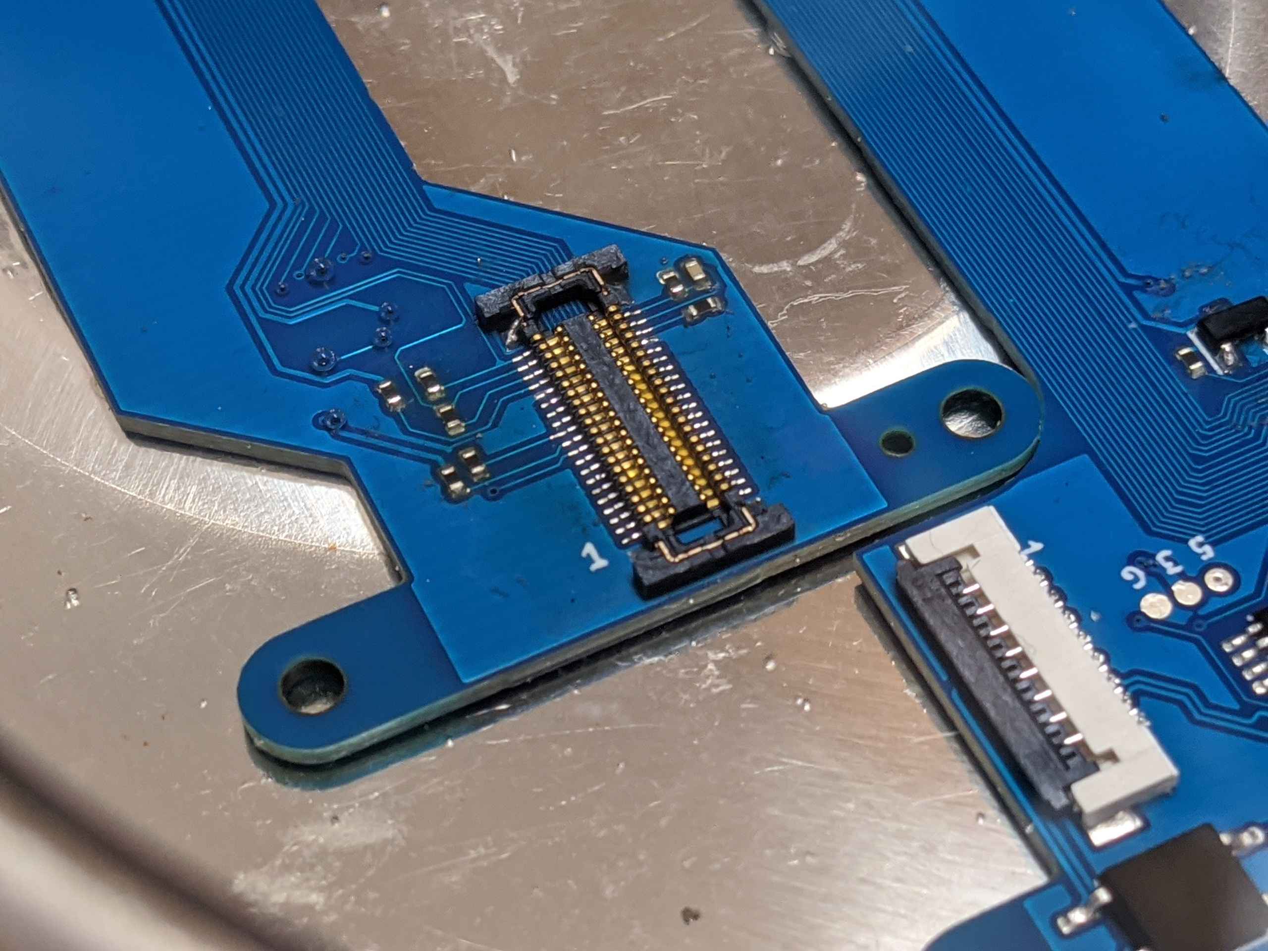
Connector comparison
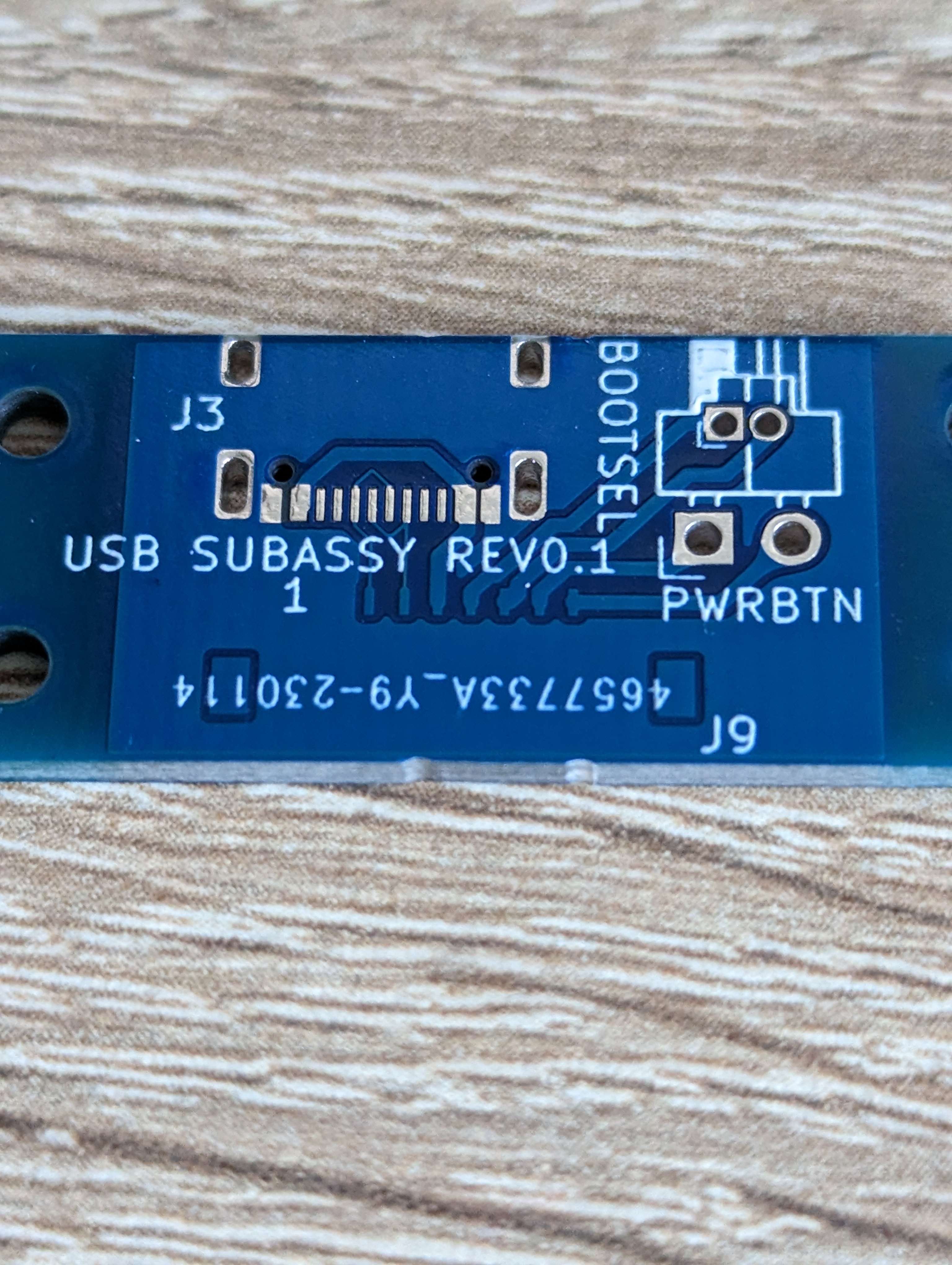
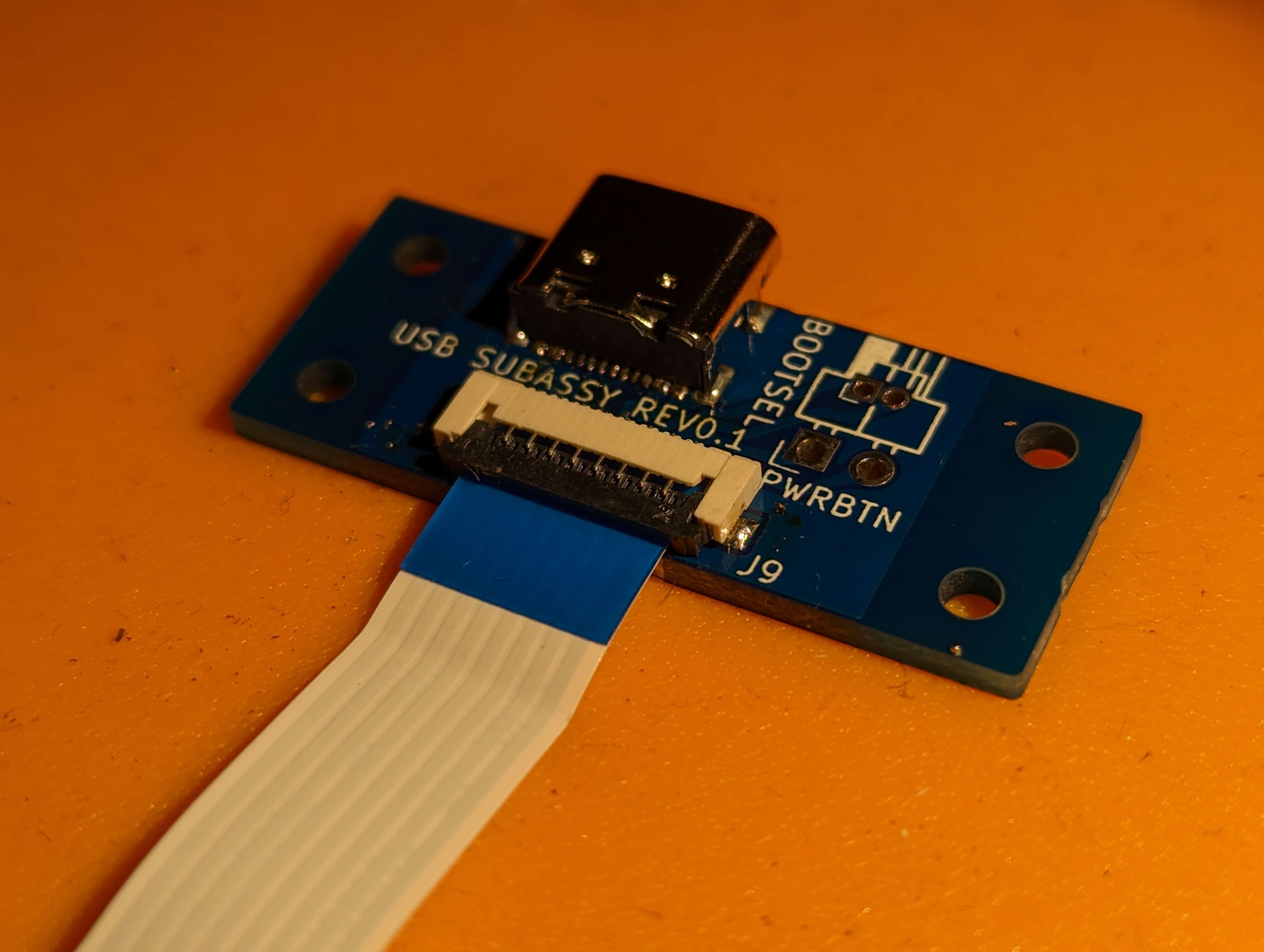
USB card, I messed up and did not remove the solder mask of the FPC connector footprint. Lots of hand scraping later and I had a good PCB.
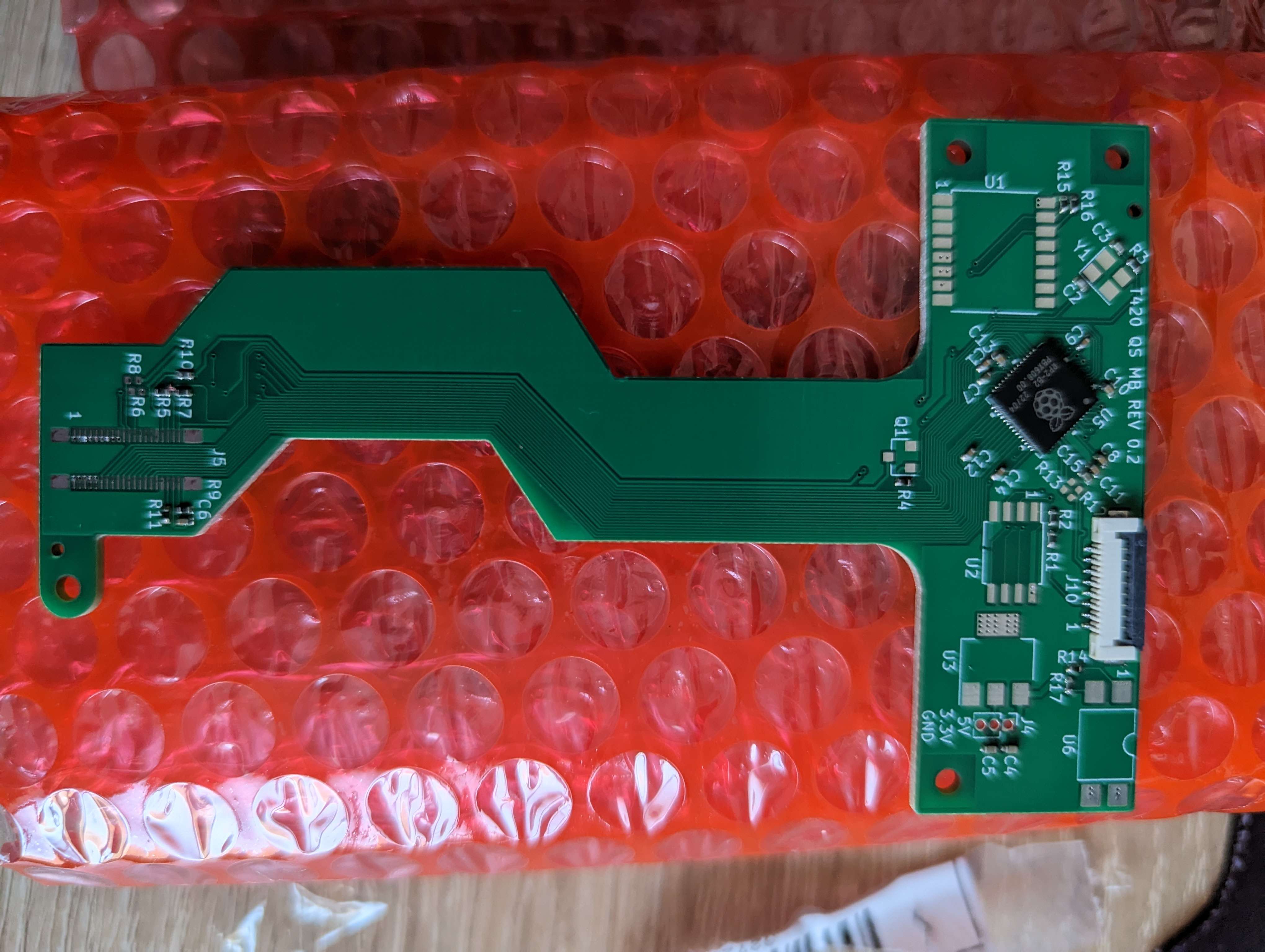
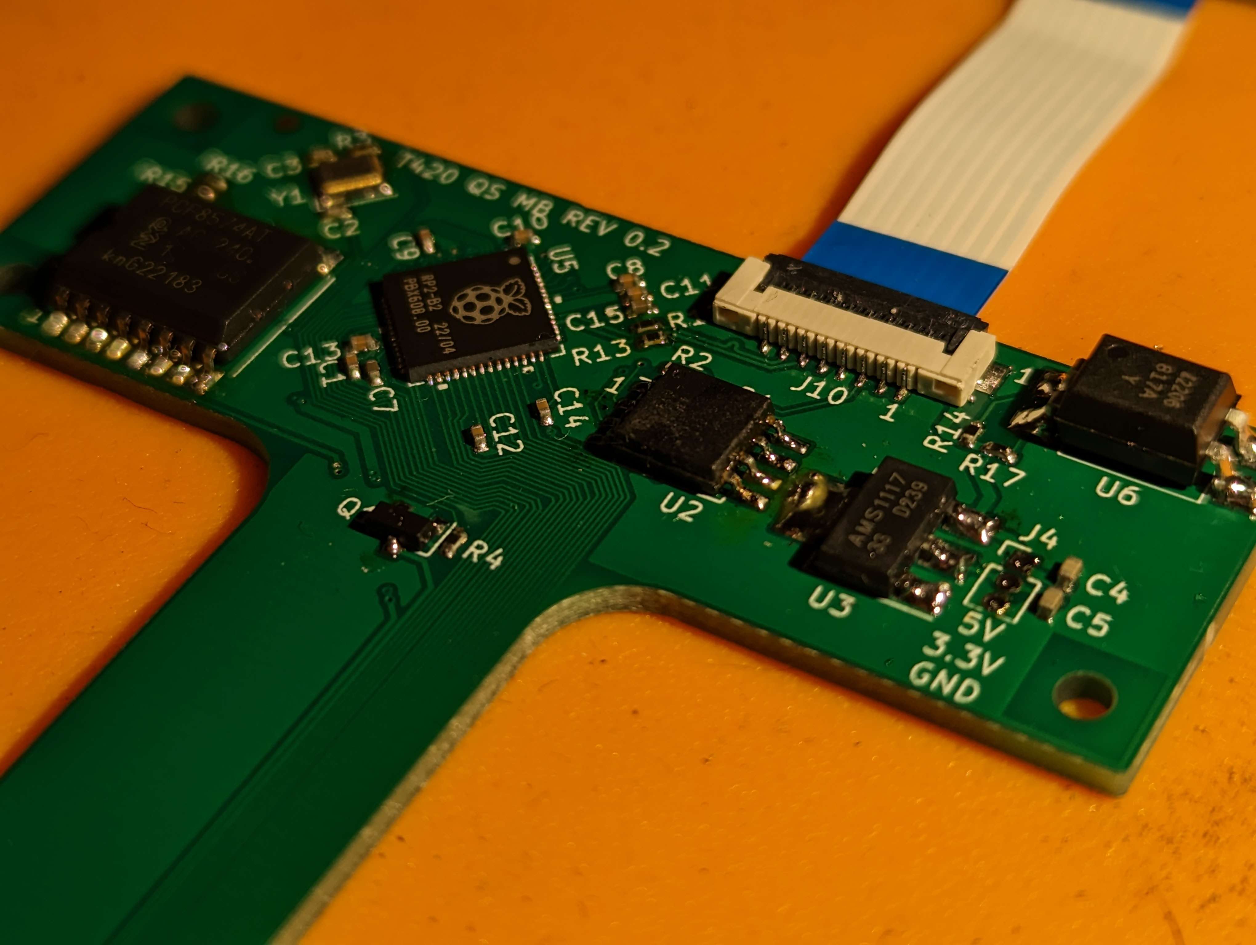
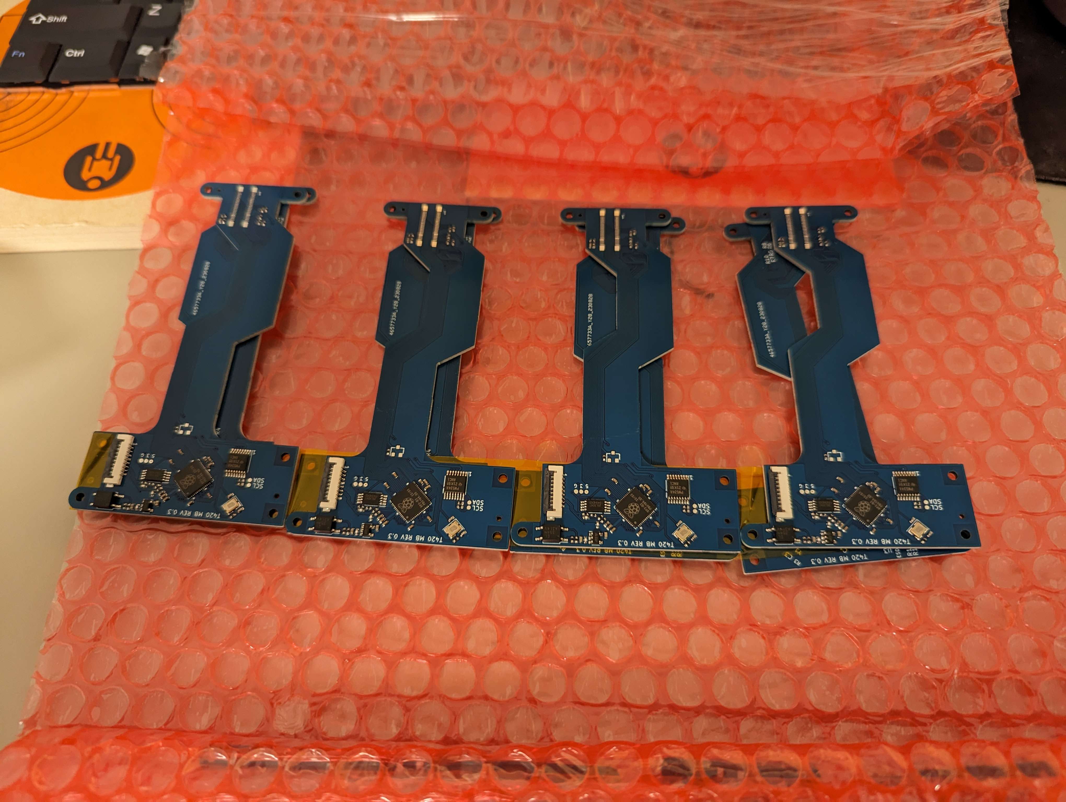
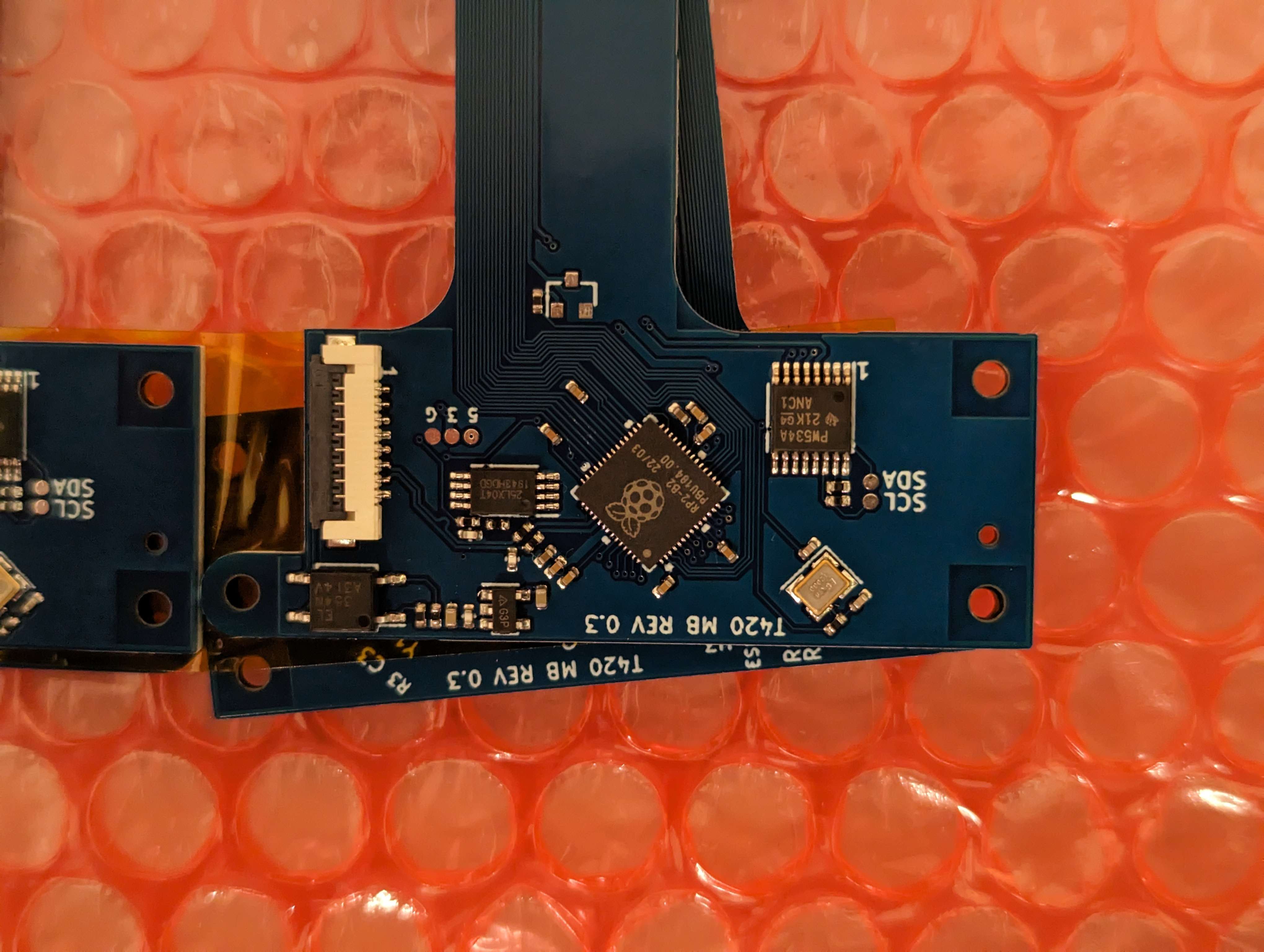
In this revision the primary goal was downsizing. Replacing the parts in bulky packages with adequate smaller parts to accomodate a slimmer case and smaller PCB size.
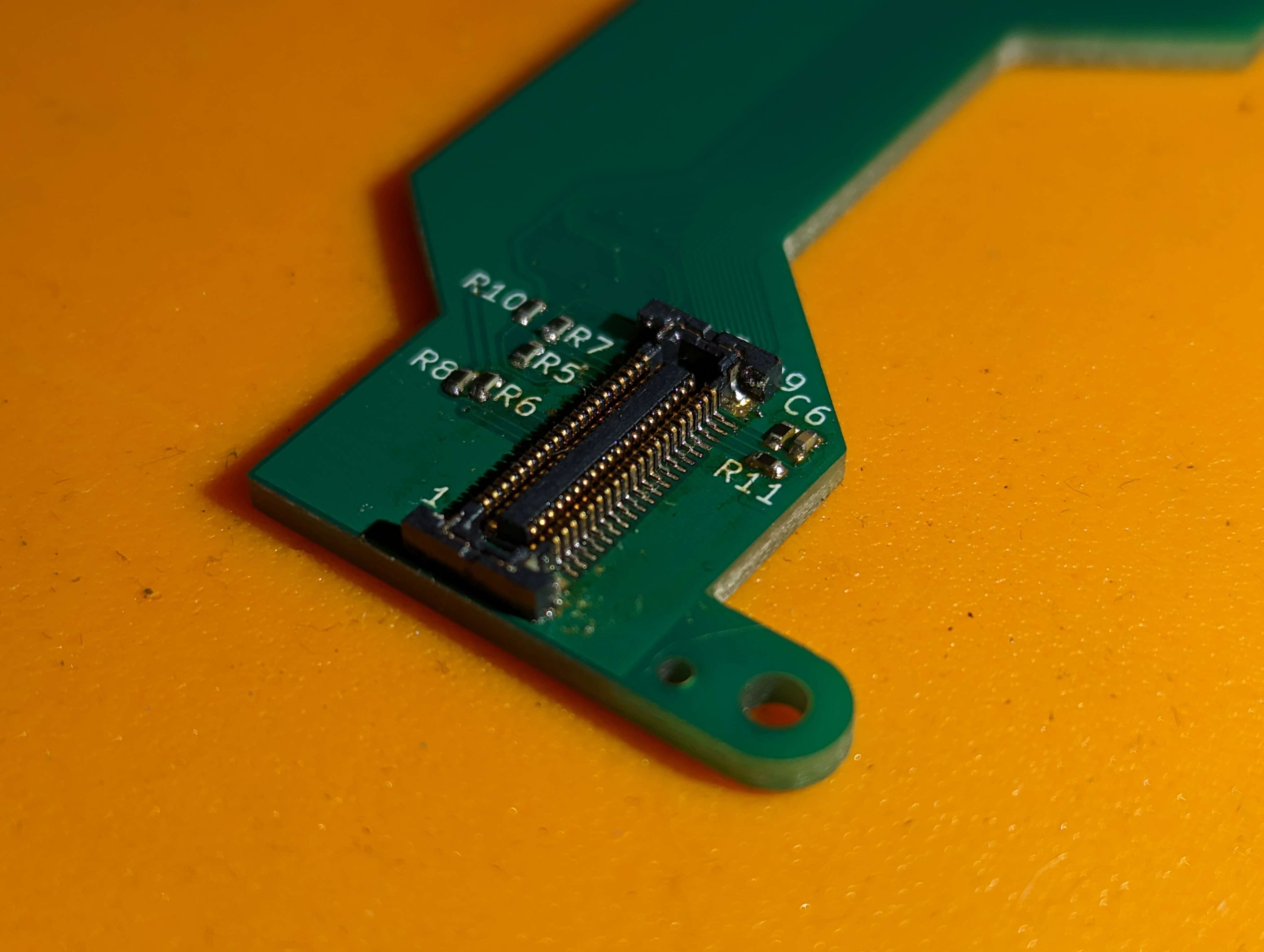
First to go was the optocoupler - as it was the thickest part, soon after that the voltage regulator and eeprom followed. Smaller parts were selected, and the board shrunk. FPC location was also moved to suit
being at the rear edge of the chassis. ESD clamps were also added to the USB lines, along with the power button being connected to the IO expander as well as the optocoupler for future use.
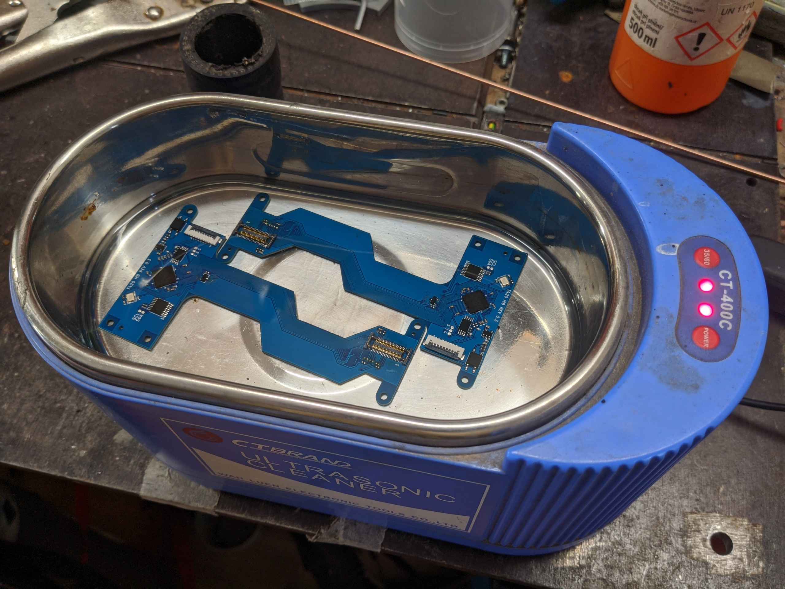
The optocoupler is broken out next to the USB connector so it can be used with a desktop PC's power on circuit. Yet again the PCBs were mostly assembled by JLCPCB Assembly with the rest done by hand by me.
Assembled boards in the ultrasonic cleaner.
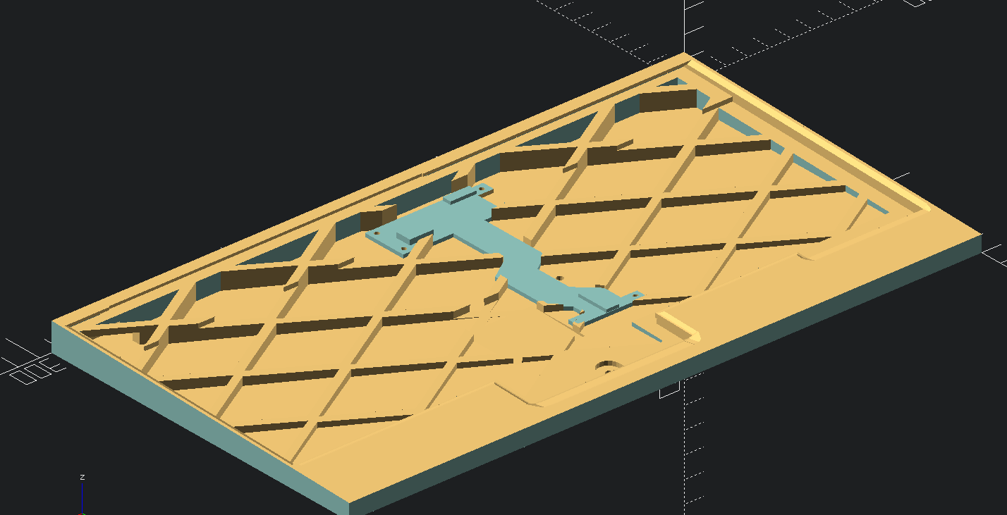
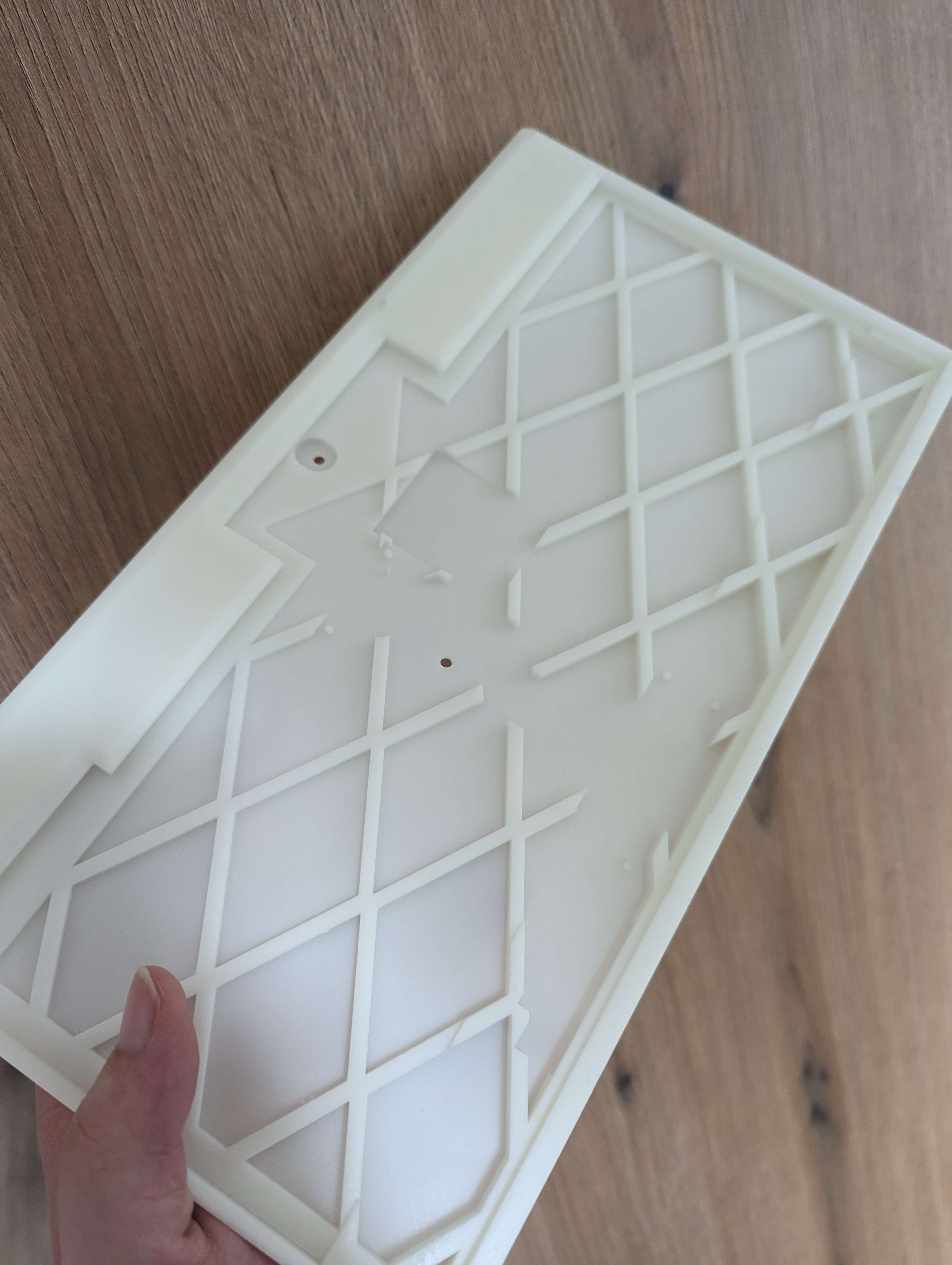
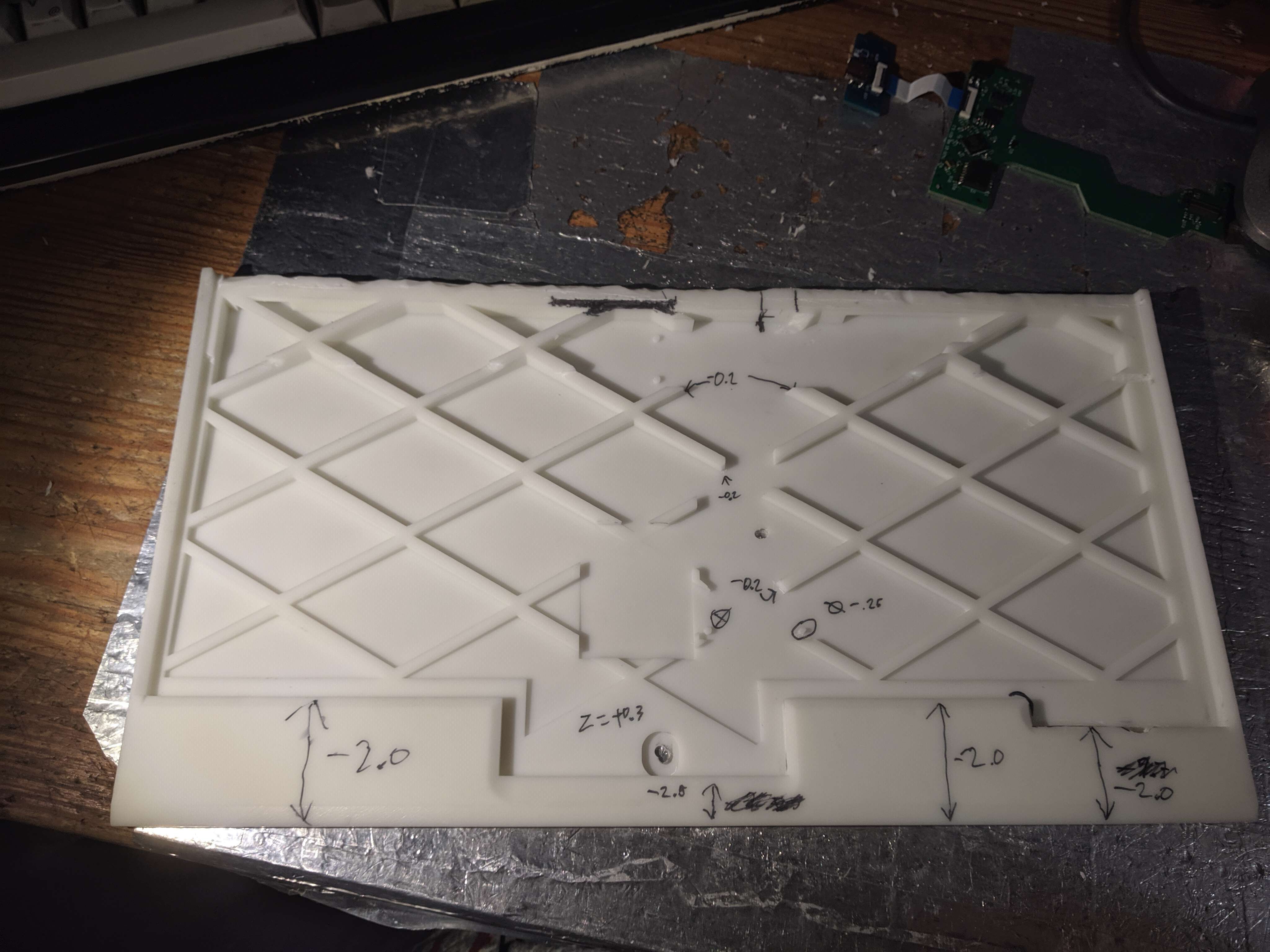
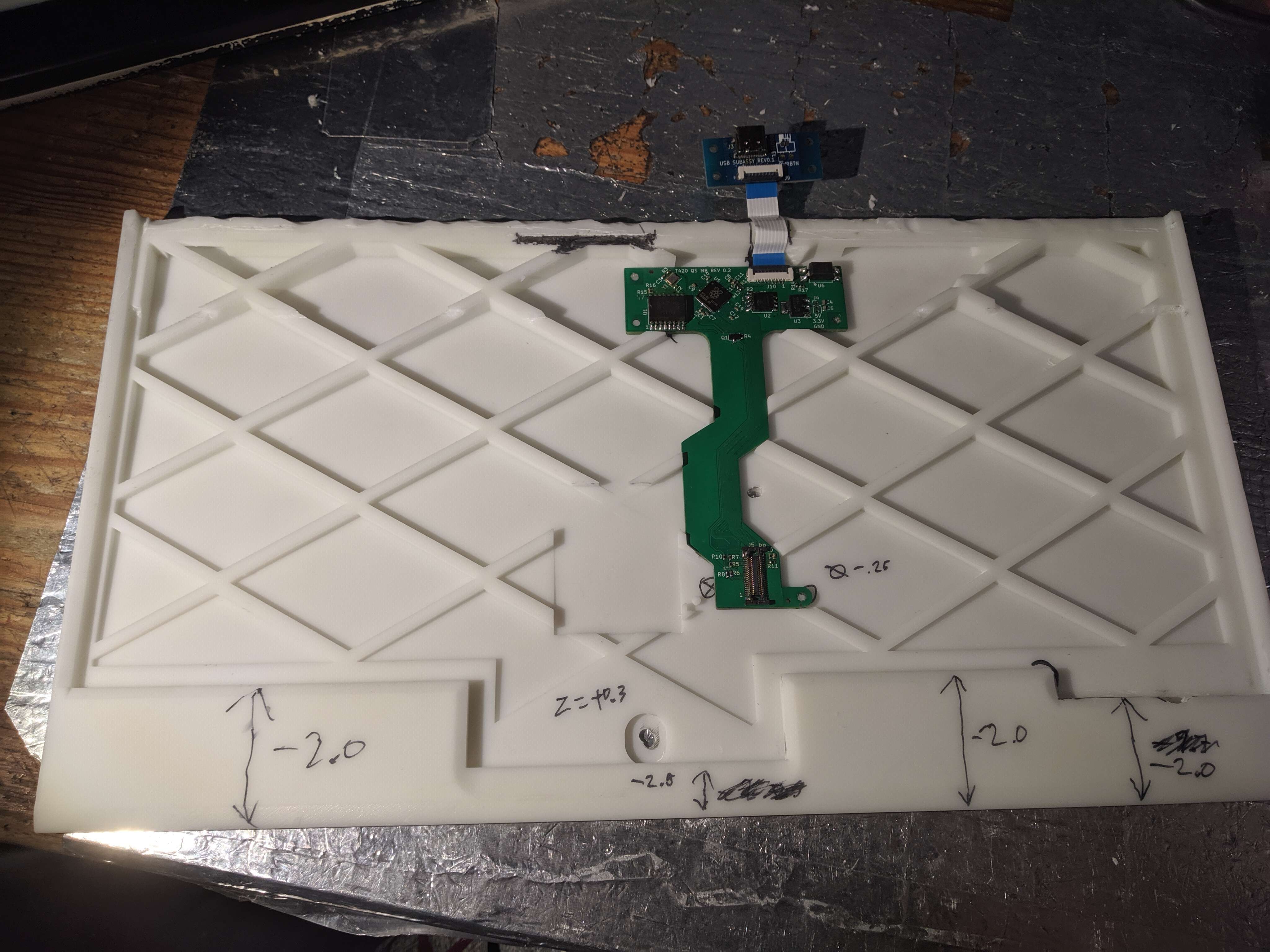
The casing has been nothing short of a nightmare. At first I went for a one piece design, but getting the tolerenaces right for the keyboard to slide in like the original laptop
has proven to be beyond my means. This type of design is also unmanufacturable at a mid/larger scale, it can only be effectively produced on a 3d printer due to overhangs. Industrial SLA printing quality
is spectacular, and offers easy mid-run revisions unlike an injection molded process. On the other hand the cost per case is about 20 euro/piece at minimum. Two of these SLA printed cases were made,
I have been using one of them daily with the rear cut off to fit the keyboard. I recently attempted making a two piece design that could be injection molded, but I have yet to obtain a physical copy to check fitment.
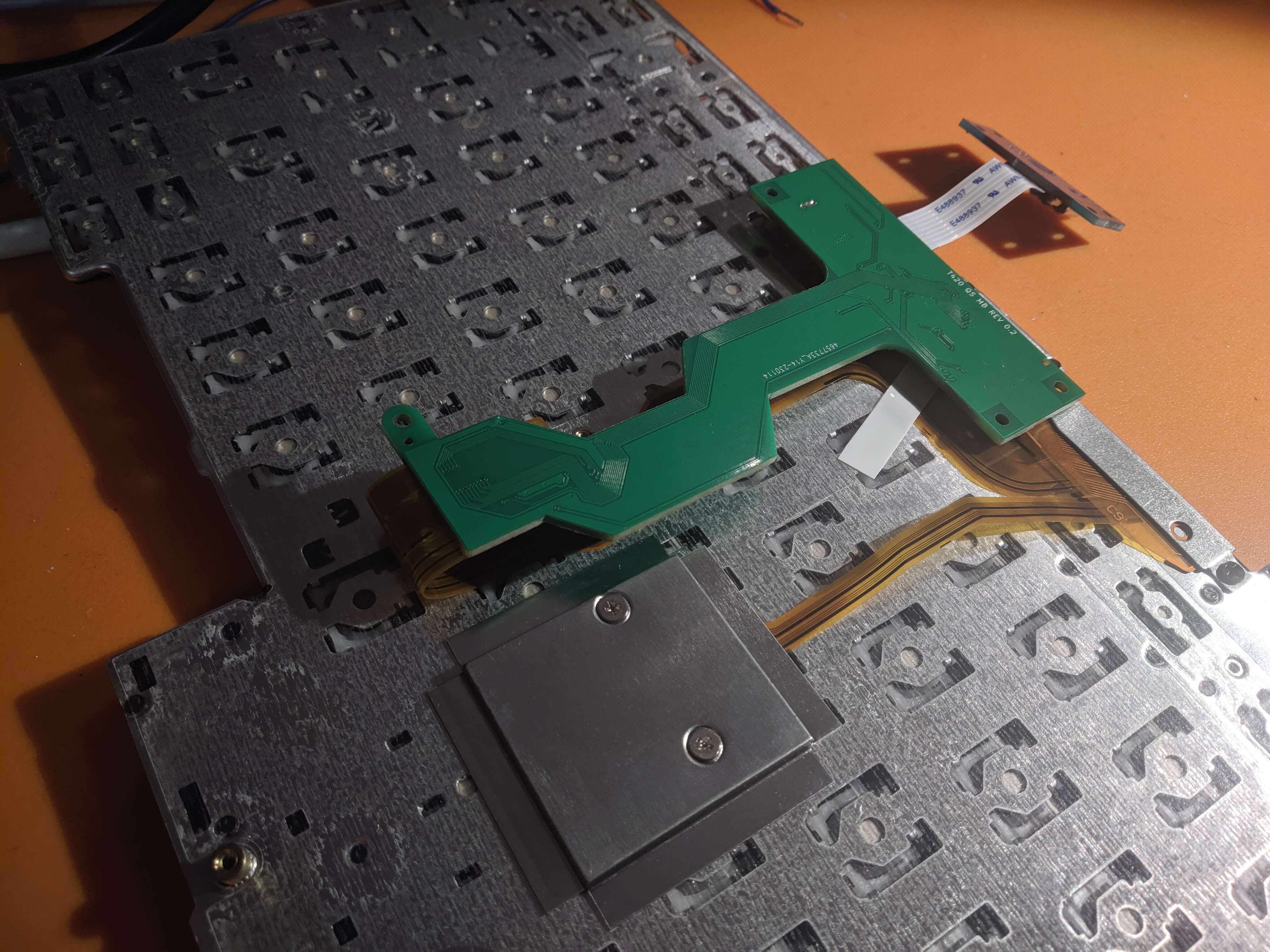
Keyboard itself is screwed down with two bolts through, the main controller PCB is held in with pegs in it's ears. The USB card is meant to be placed in a soft rubber mount to resist bending and other types
of mechanical stress that the connector can experience during use.
Page viewed best on a 1600x1200 monitor in Firefox with Terminus font and a dark background