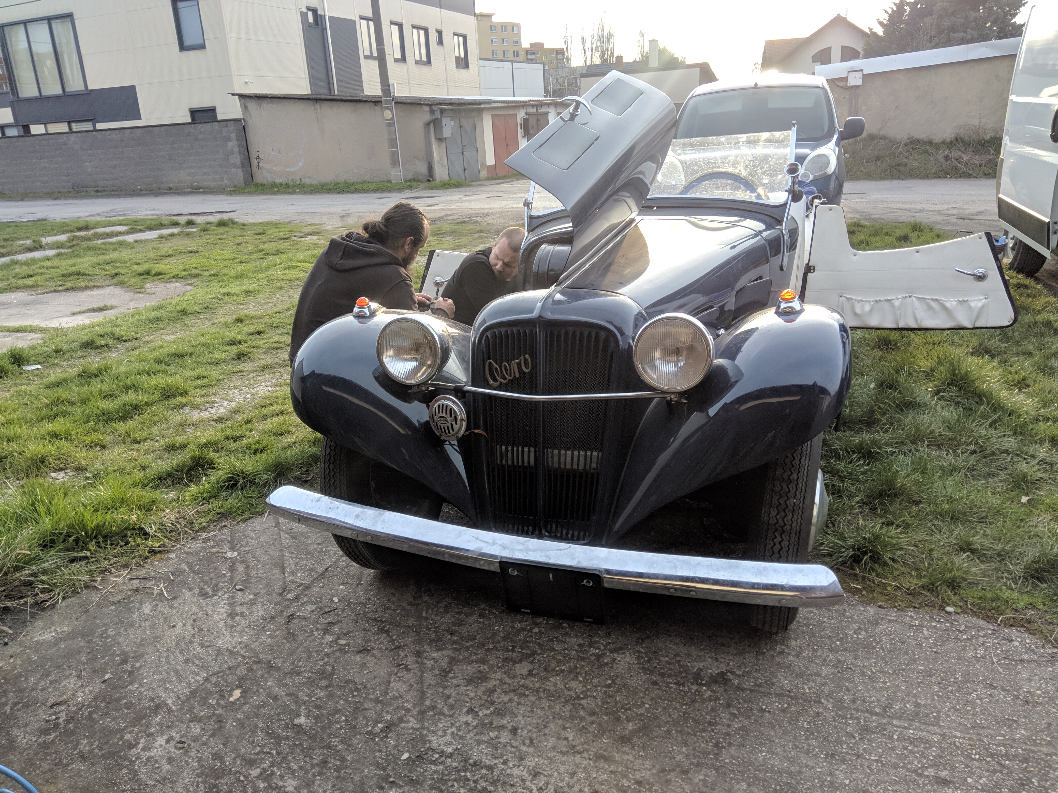
This Aero 30 is not mine, however I was asked to solve it's ignition issues. It was fitted with an aftermarket
12V alternator, and an ignition system for a Trabant. The quality of previously performed work on this vehicle is questionable at best,
ignition system included. The mechanic that has been taking care of this vehicle after has reported that he could never get the timing set reliably.
The job for me was:
-Figure out the ignition system
-Fix the current thing or create a replacement
So what even is this car and engine combo? It is a front wheel drive mid engine longitudinal setup. It is an inline 2 cylinder,
2 stroke without a water pump or any belt driven accessories.
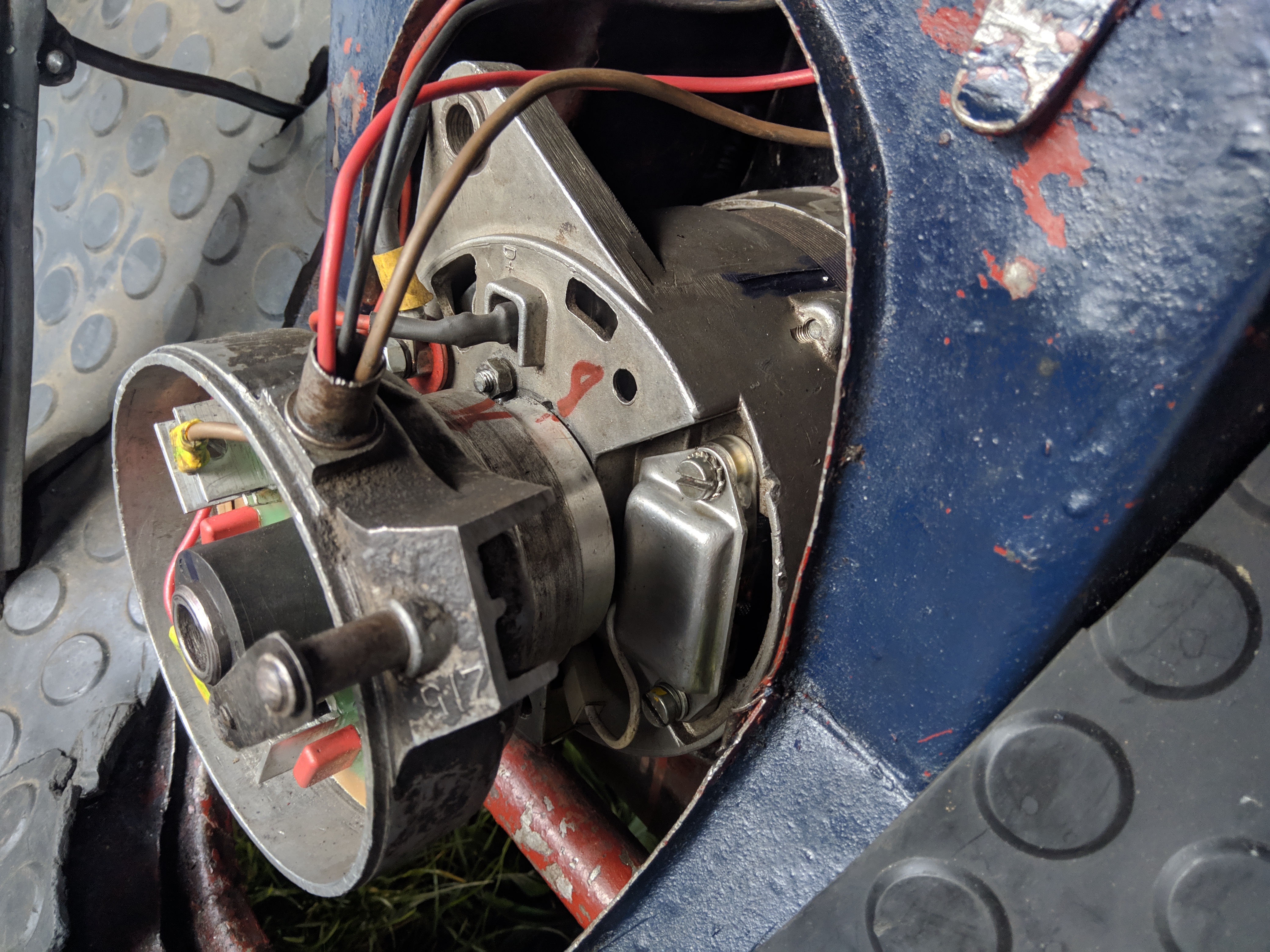
The alternator and ignition are driven off the rear of the crank - the front drive the clutch.
After looking the ignition system over, it was clear that it's a very basic setup with no real timing adjustment, and a
large number of non-standard parts.
I figured that I could do it better, so the specific tasks at hand are:
-Use standard automotive parts wherever possible
-Spec out ignition coils, leads, and sensors
-Design and assemble a triggering system
-Select and assemble an ignition controller with timing adjustment
-Design and assemble a wiring harness
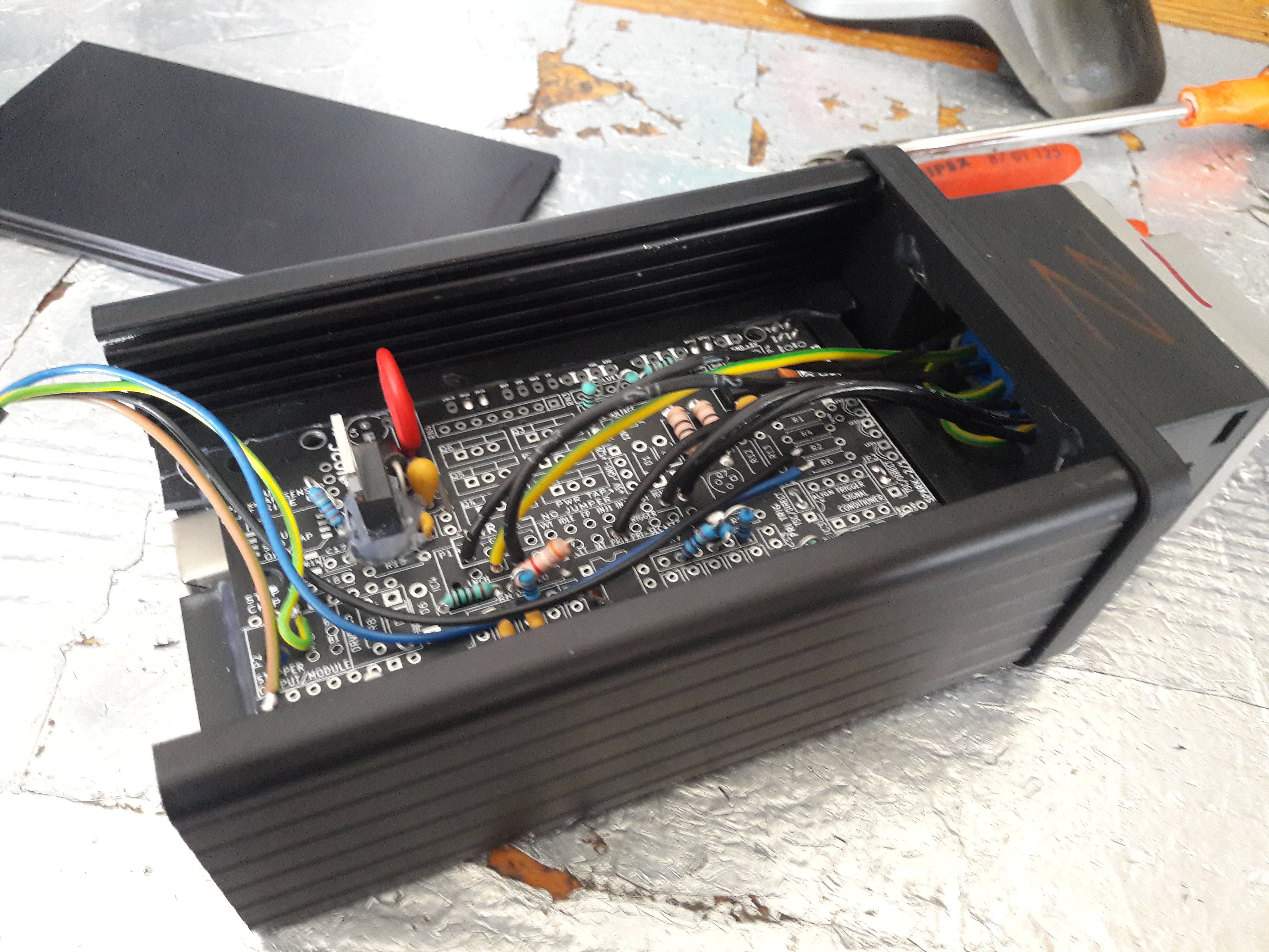
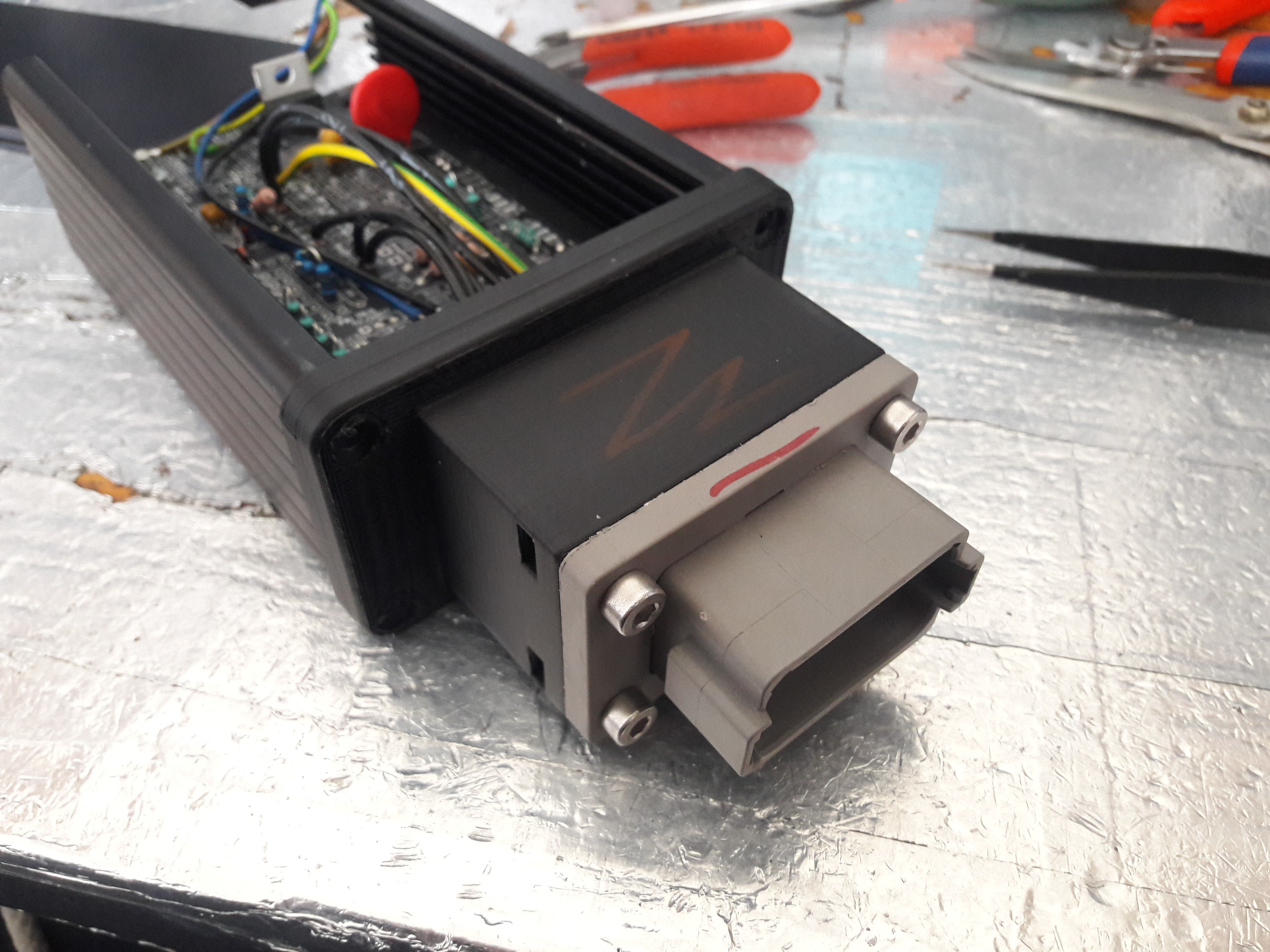
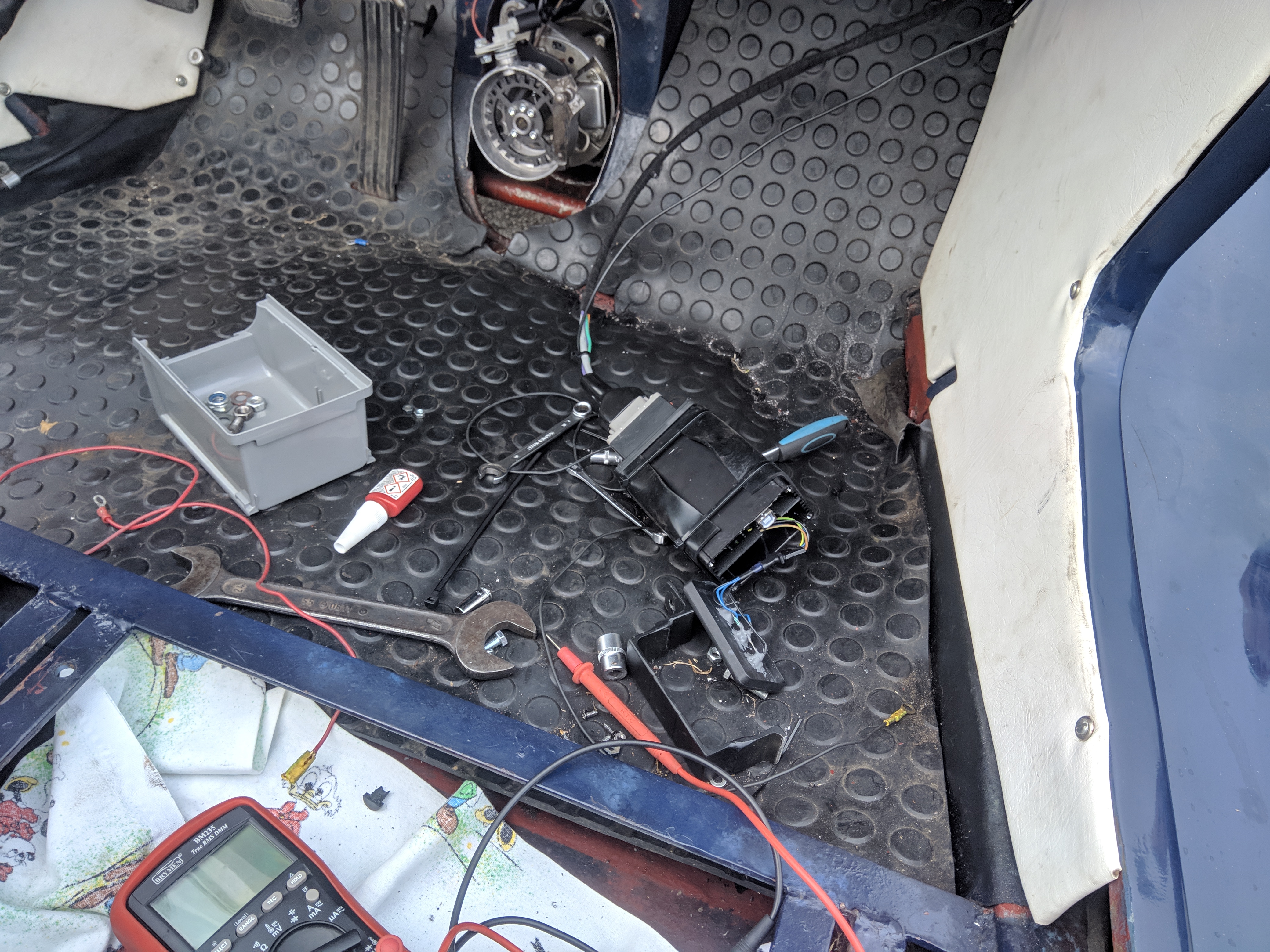
For the ECU I decided to go for a partial NO2C speeduino compatible board. It is compact, simple, runs speeduino which has proven itself to me,
and I already have a bunch of PCBs on hand. Electrically only the ignition output section, voltage regulator, and battery voltage measurement, are populated.
I also populated a few resistors for sensor inputs that aren't utilized so that they don't float in non-sense values. Mechanically, it is mounted inside a Hammond aluminium
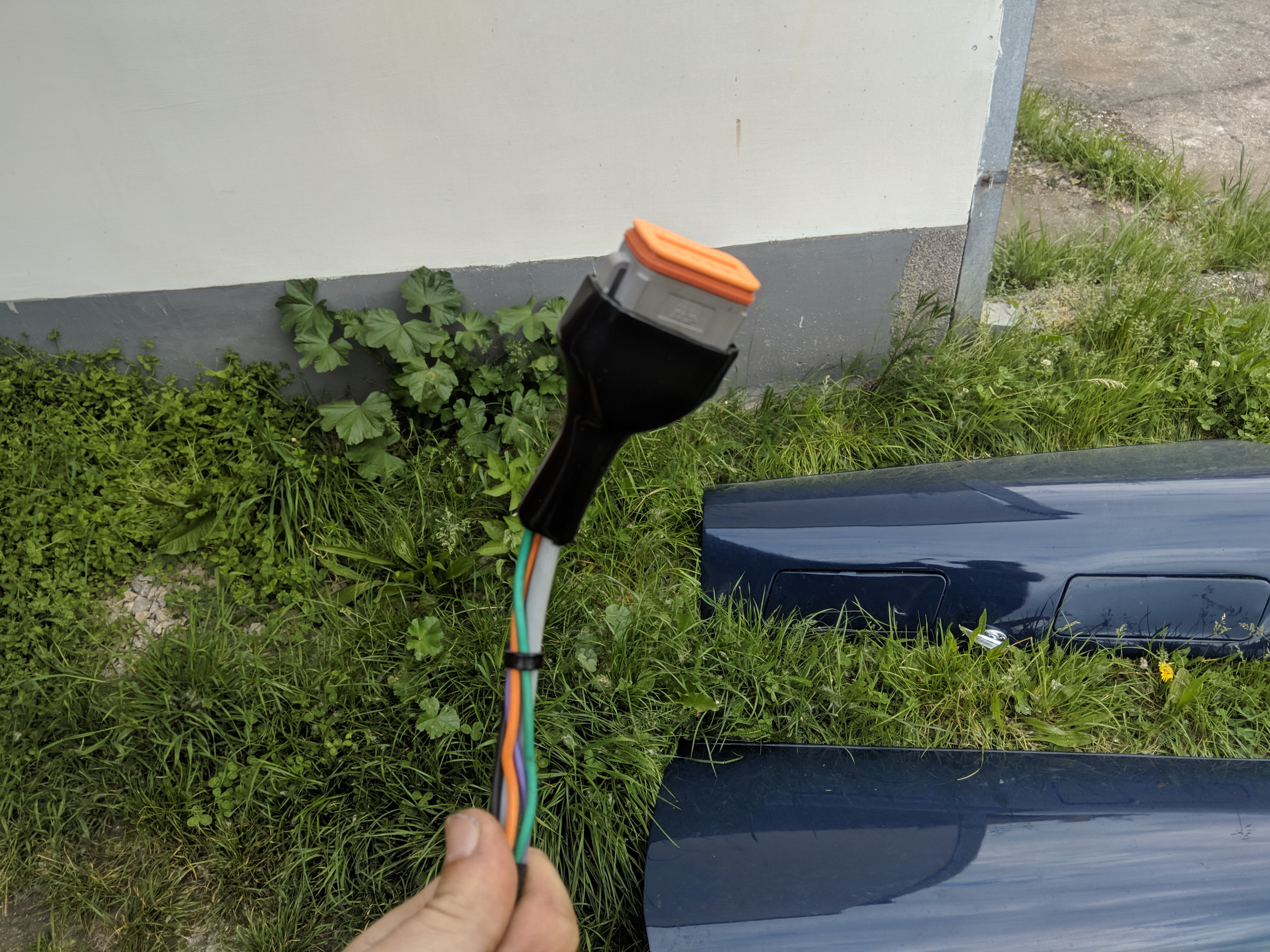
extruded casing with a 3D printed cover to hold a Deutsch DT style 12 pin flange connector. I added a power LED, and ignition output LEDs onto the other side panel.
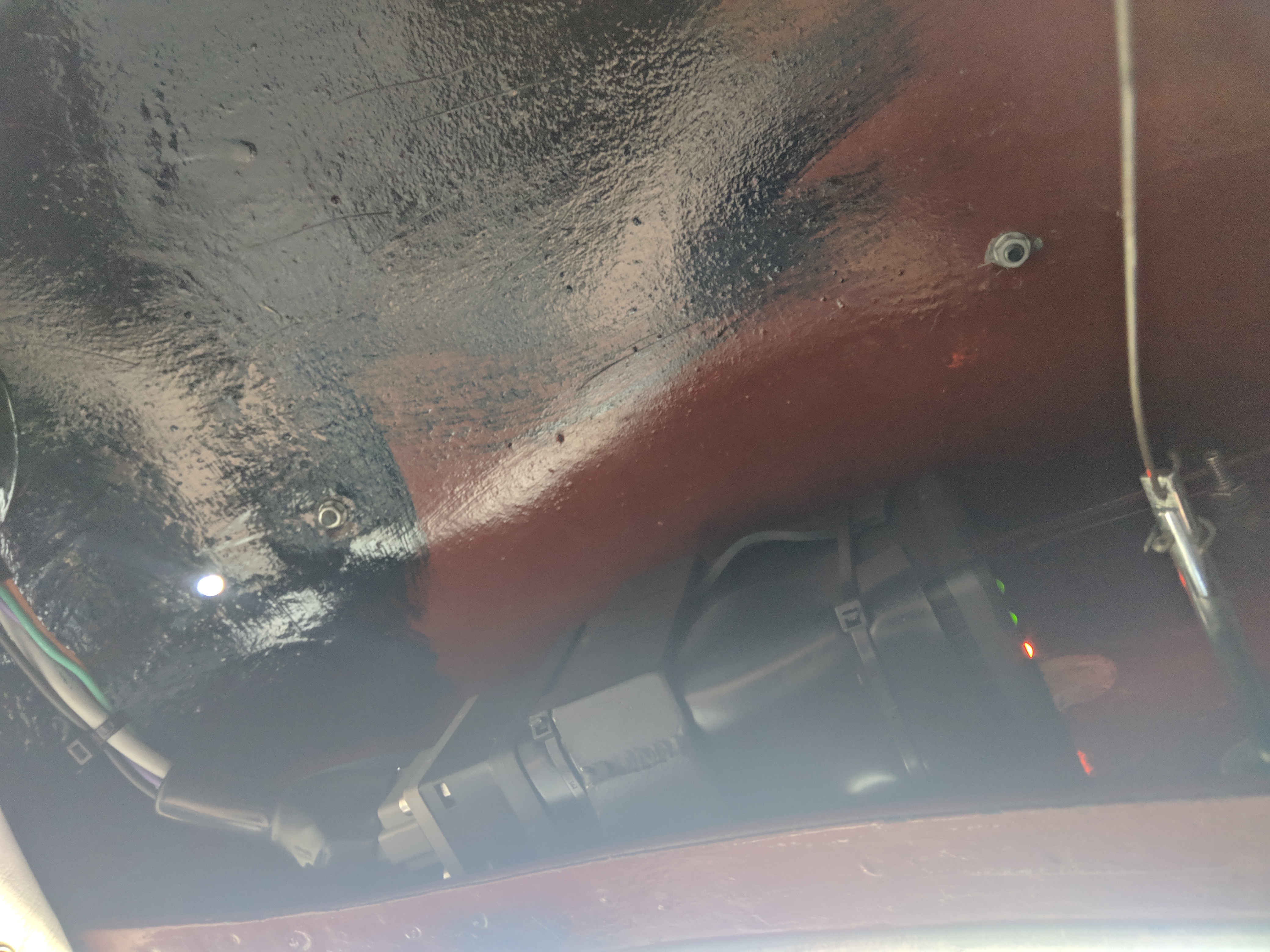
The final ECU is mounted behind the dashboard with a bracket that I welded together while the wiring tucked behind an interior panel.
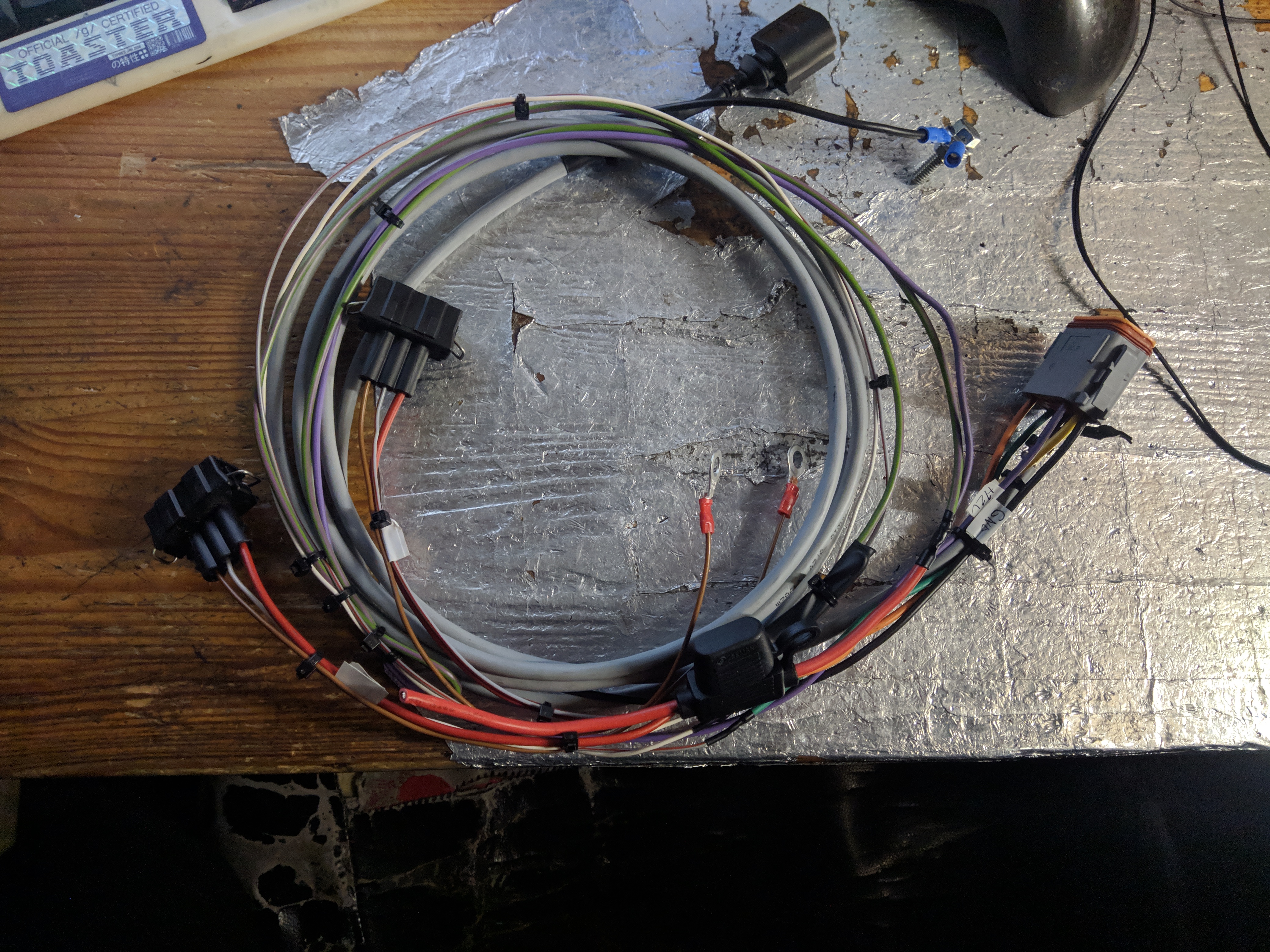
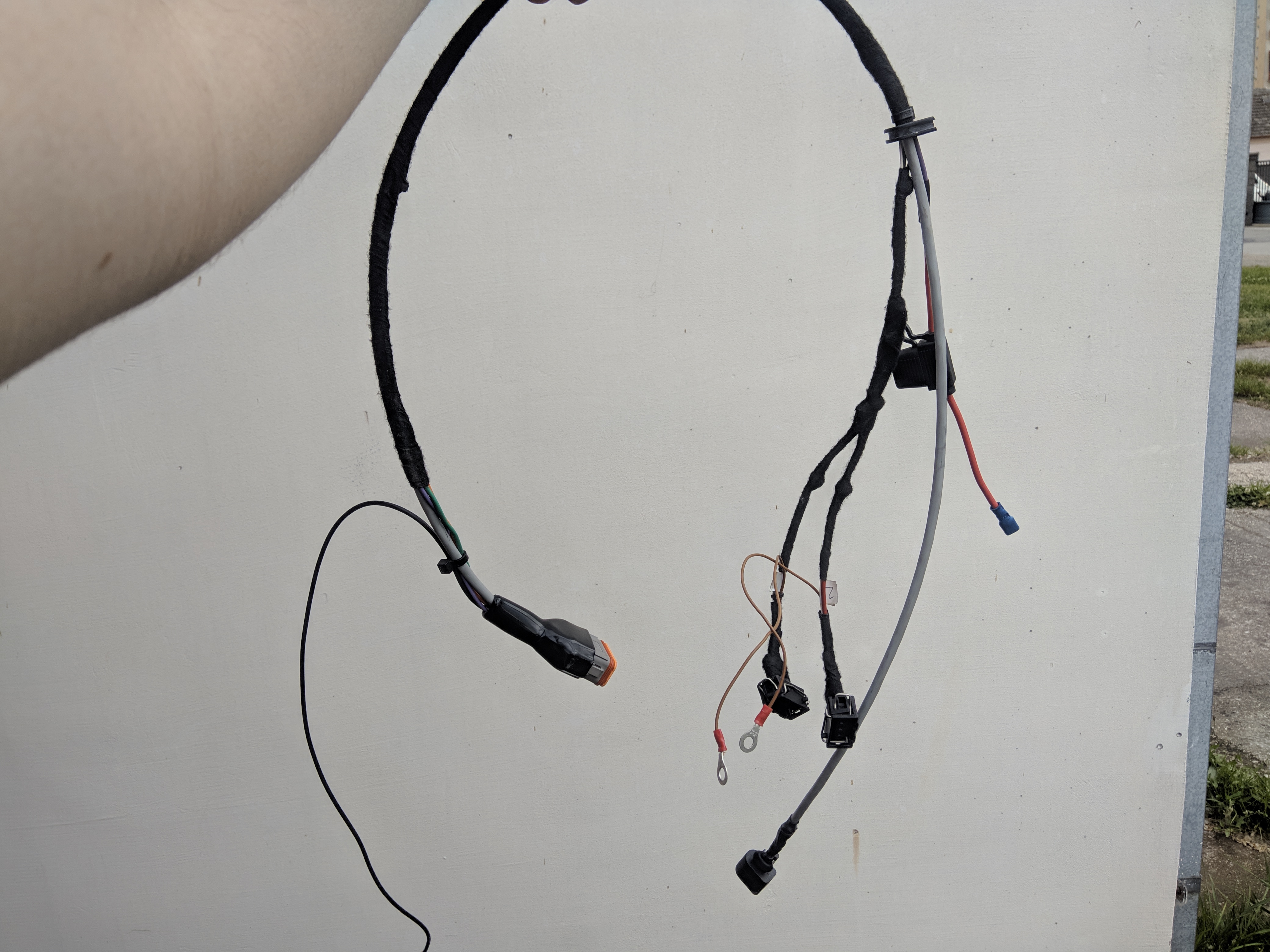
This harness is quite simple, I brought a long version on-site and shortened the end to fit the final mounting location. It is protected by cloth tape. I have recently started primarily using heatshrink after many experiments with various methods, but the tape was more efficient and much easier to do on-site. For power there is a direct permanent feed from a terminal on the alternator, going to a relay and the relay is switched by a spare switched output in the original fuse box.
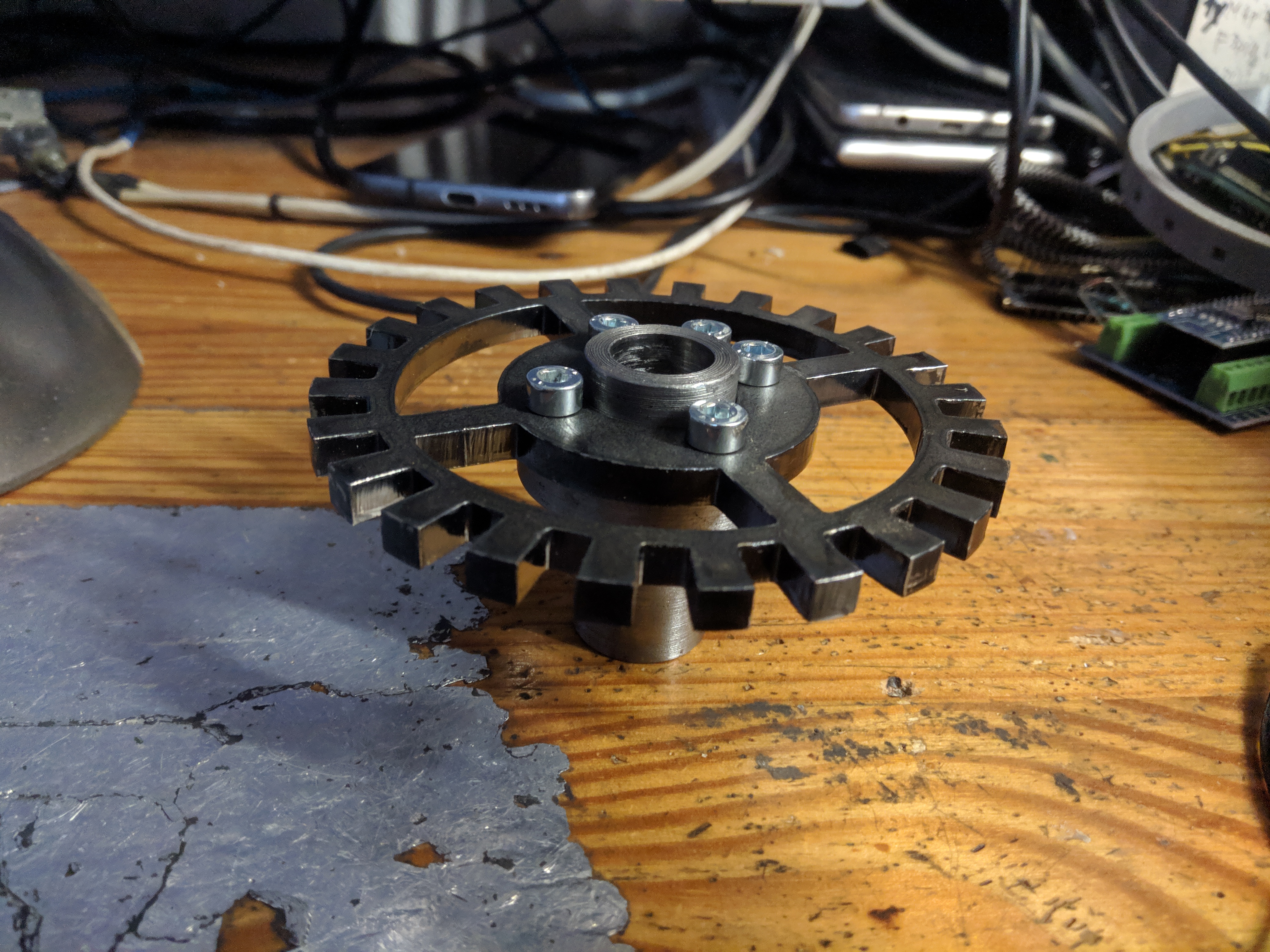
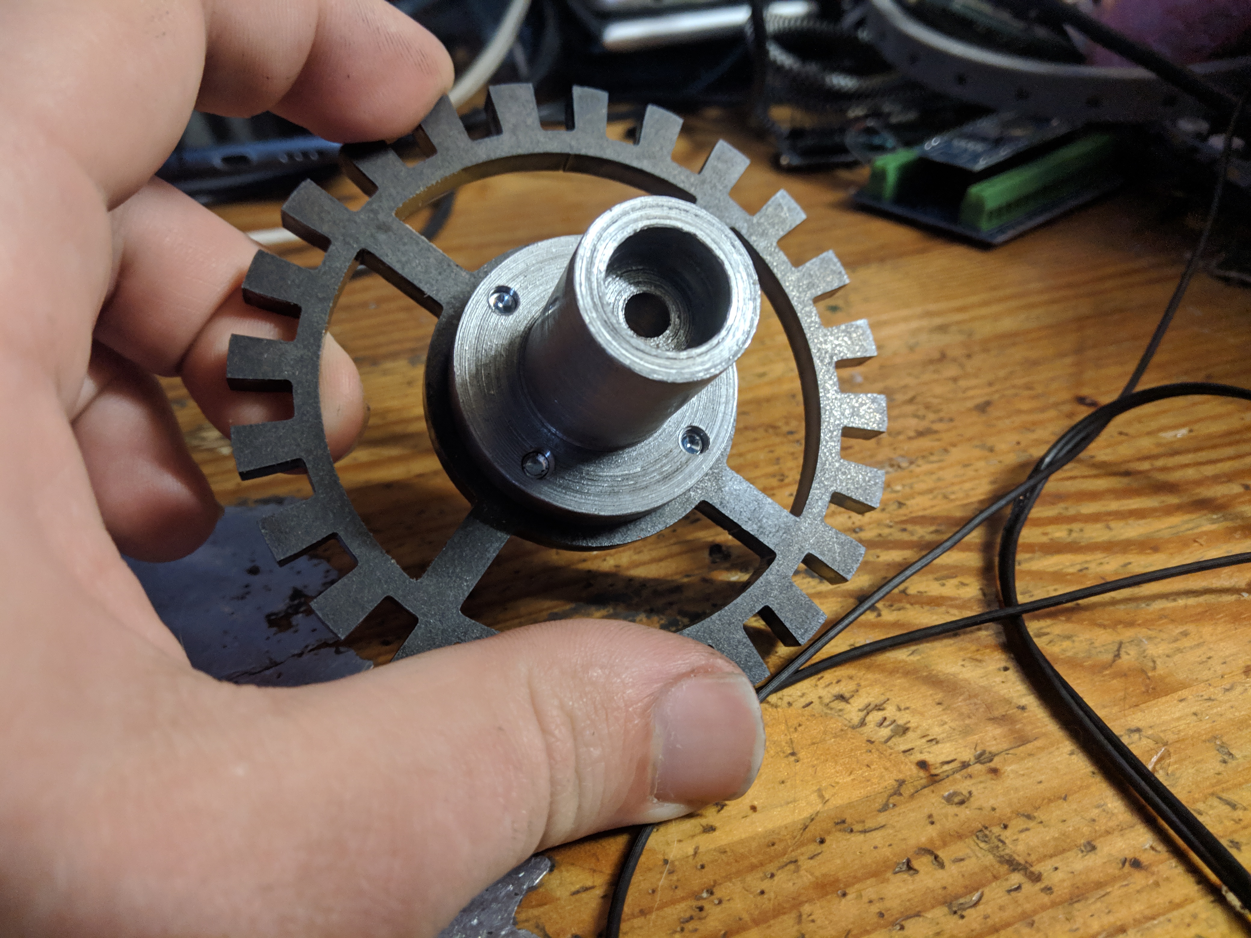
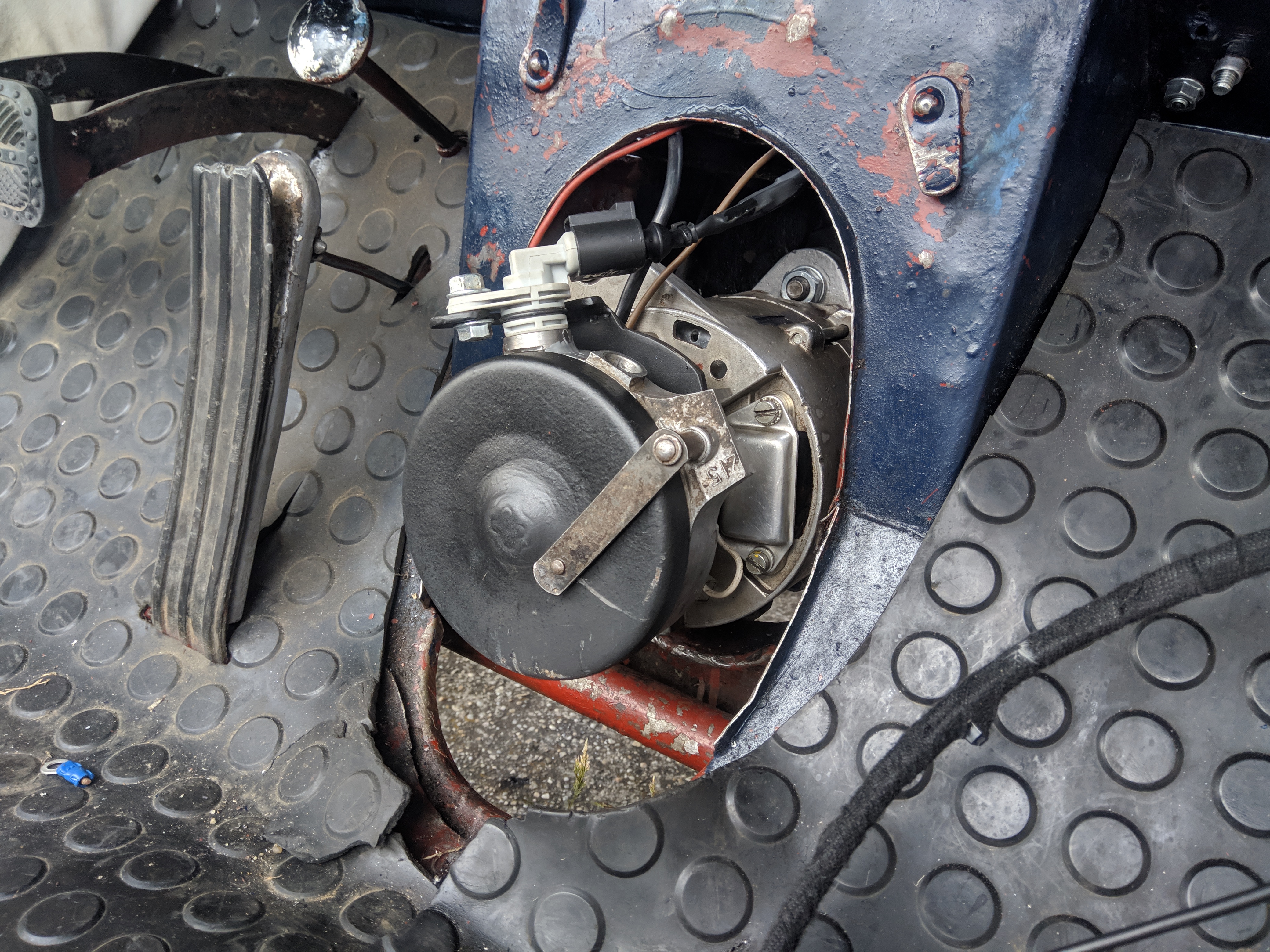
For the triggering I utilized the Trabant ignition housing and replaced it's internals. New shaft, and trigger wheel
were mounted inside, and a new sensor
was mounted to the side. At first I had the shaft, trigger wheel, and sensor spacer ring made on a 3D printer to check
fitment, after fitment was confirmed I
proceeded to manufacture the metal parts. Trigger wheel was laser cut, spacer and shaft were turned on a lathe. I had
the machinist make the shaft without any
holes for the trigger disc, I drilled those one by one always bolting down the disc with the newly created thread. The
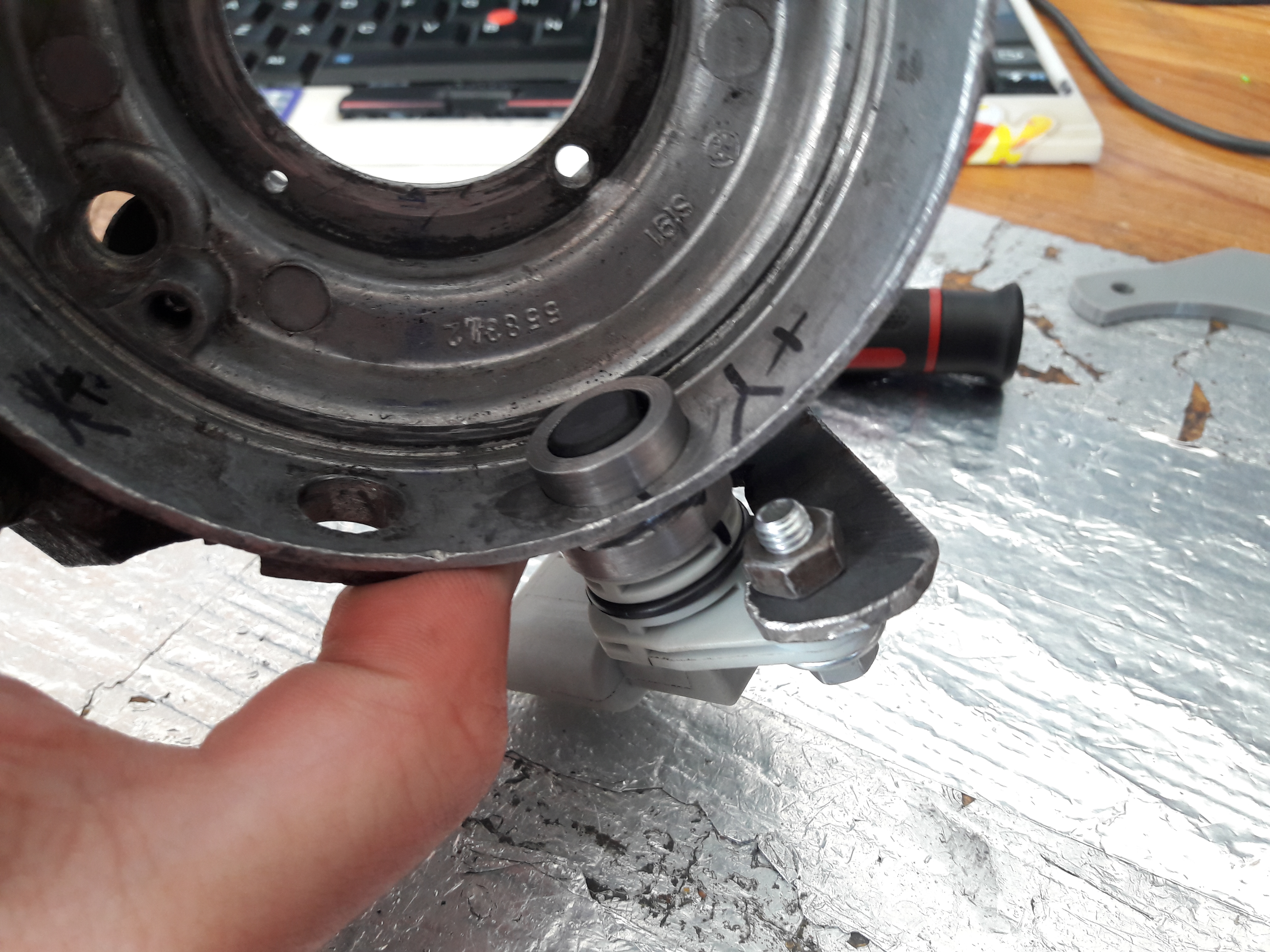
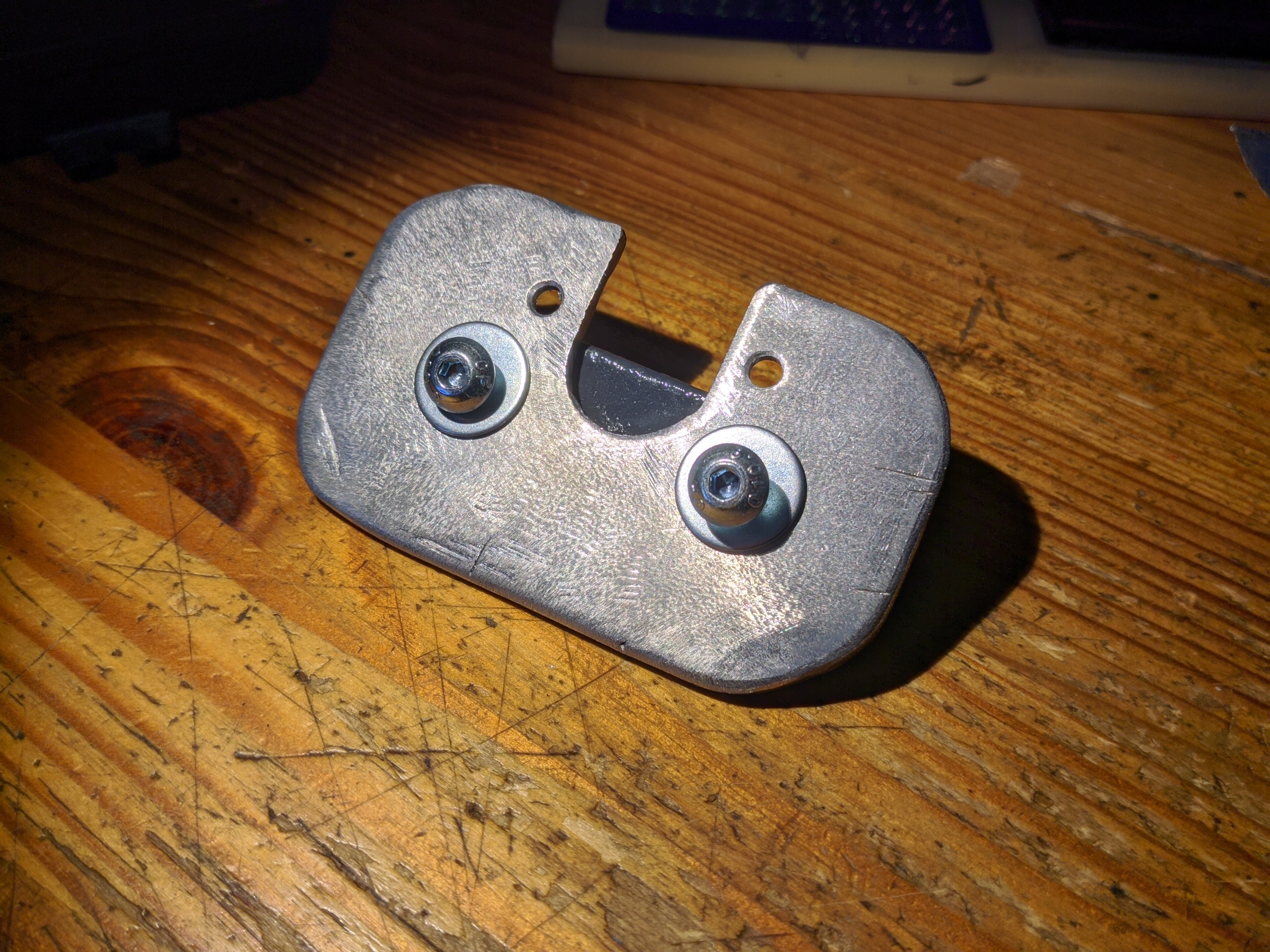
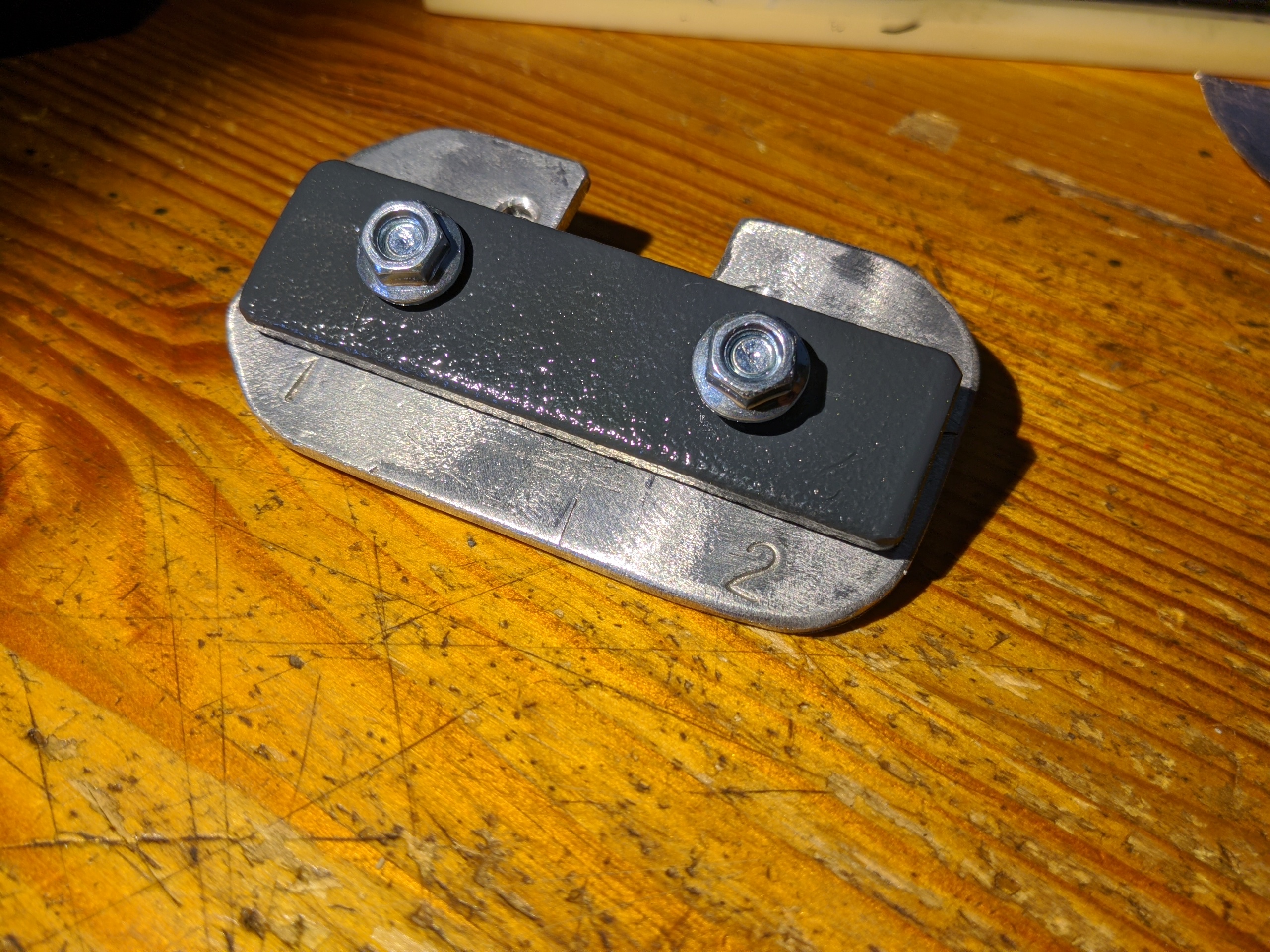
position sensor is located with the spacer,
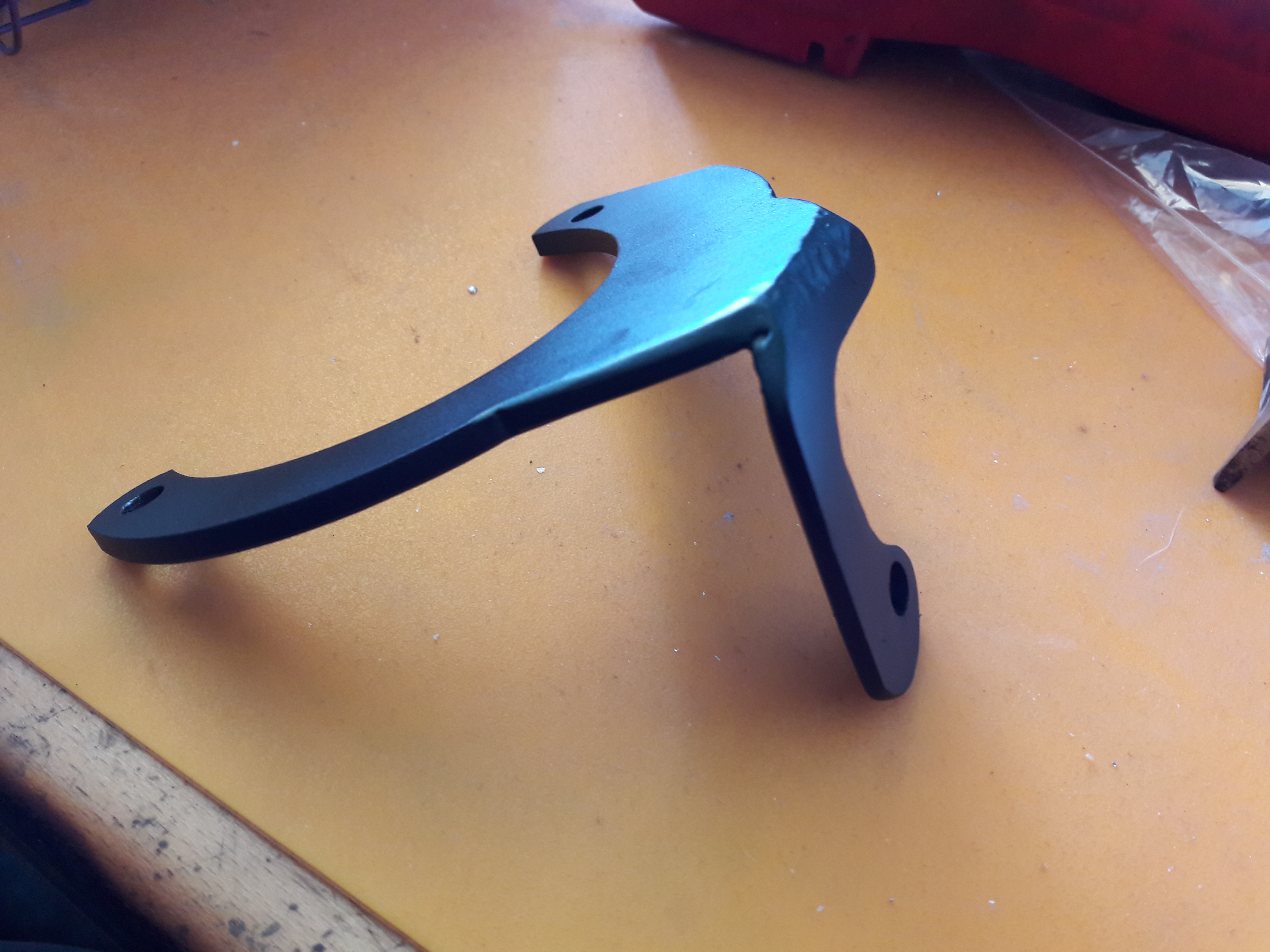
and secured in place with an external bracket.
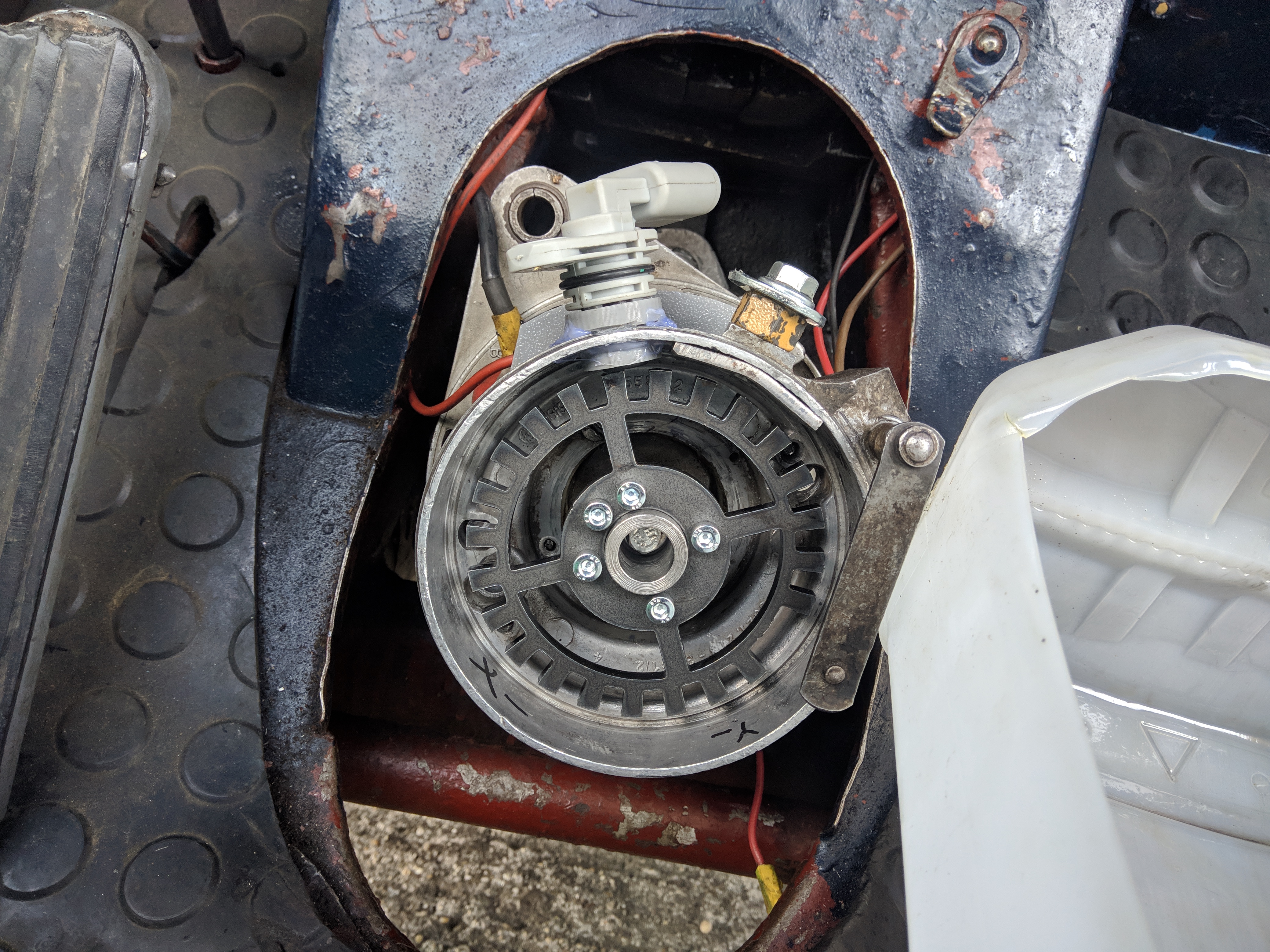
During the first test run I noticed an issue with the shaft, it rocked back and forth. Turns out the previously
done alternator conversion was done improperly and the shaft's flange had excessive play in it. I solved this with thin
copper shims to get a snug fit.
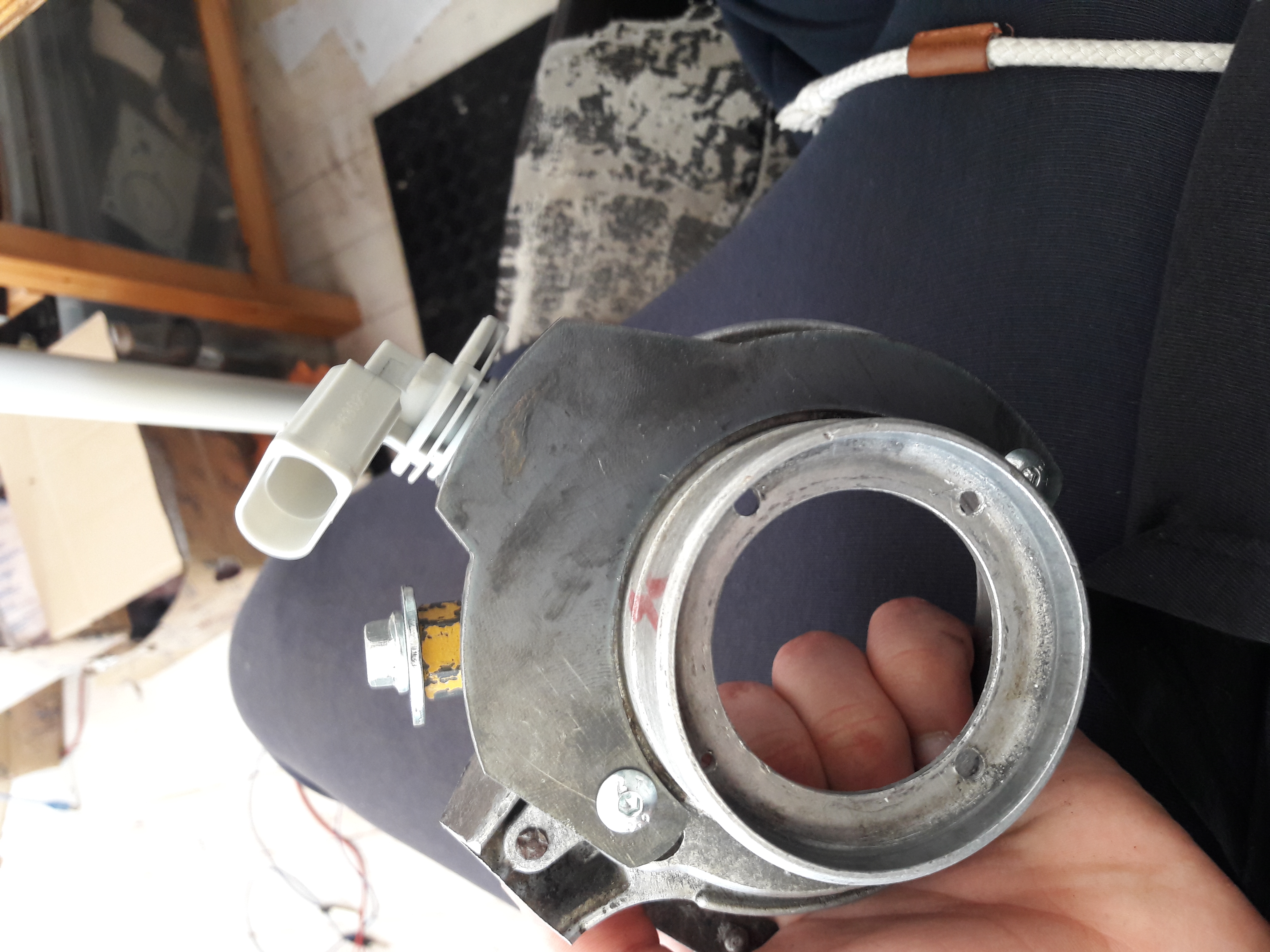
Original ignition coils were classic dumb coils, I chose to go with integrated ignition modules with the igniter and coil in one brick. This means no messing about with igniters. Instead of an outdated thread in style ignition lead, a more modern snap-in distributor style plugs are used. Ignition leads are noise supressed universal leads cut to length and capped off with an NGK right angle resistor cap. Spark plugs were also replaced in favour of NGK plugs over the previously installed Bosch plugs of unknown condition.
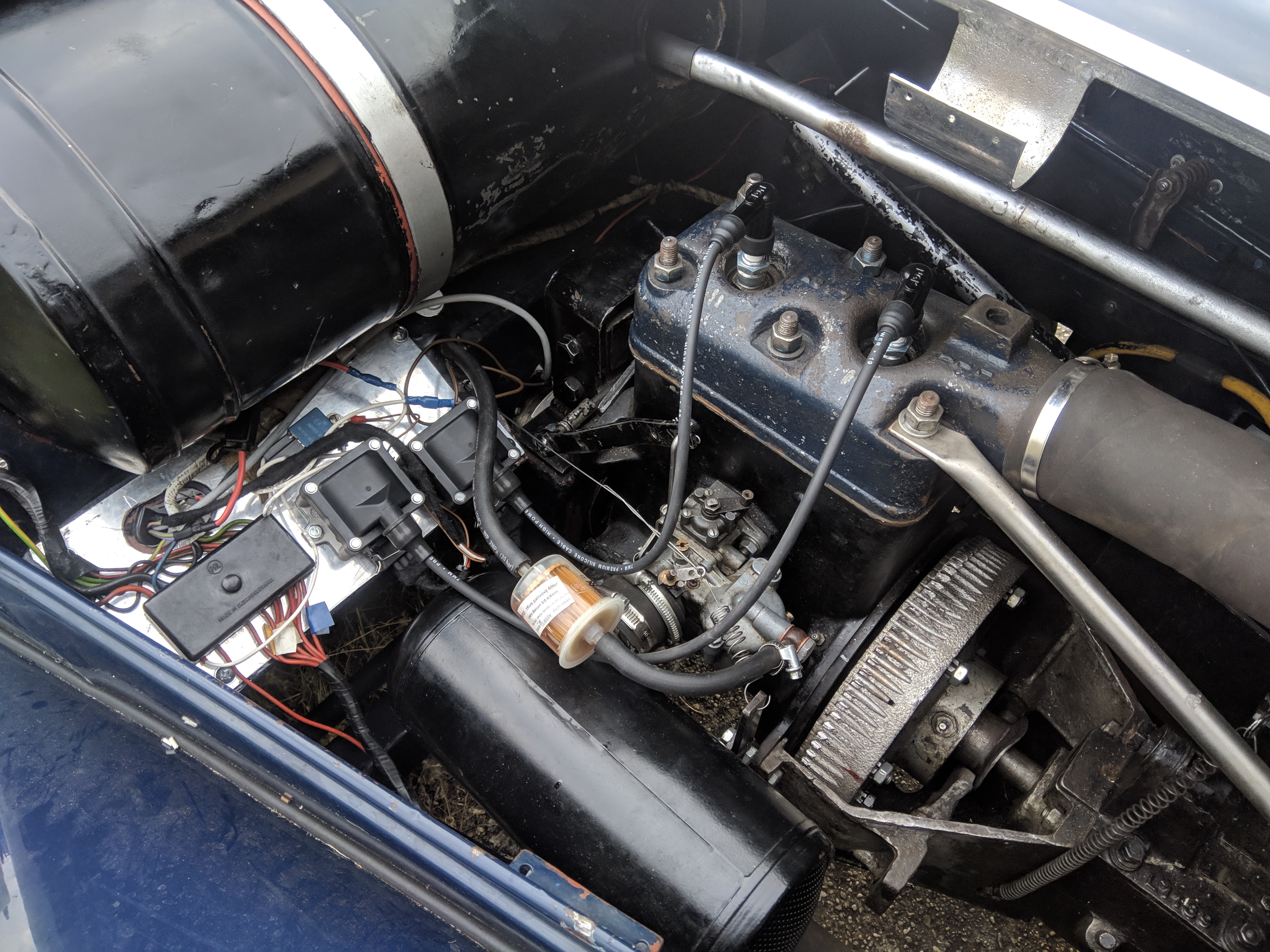
For the first test run the ignition coils were held in together on one bolt in original sheet metal, the harness was nowhere near finished, and the position sensor was purely friction fit into it's spacer. The test run revealed that there was the previously mentioned shaft flange slop. Setting the ignition timing was quite challenging due to the poor condition of the flywheel, and very vague low contrast timing marks. In the end the test run proved that the system worked great and the mechanic was thrilled when it fired up instantly and responded to the throttle perfectly.
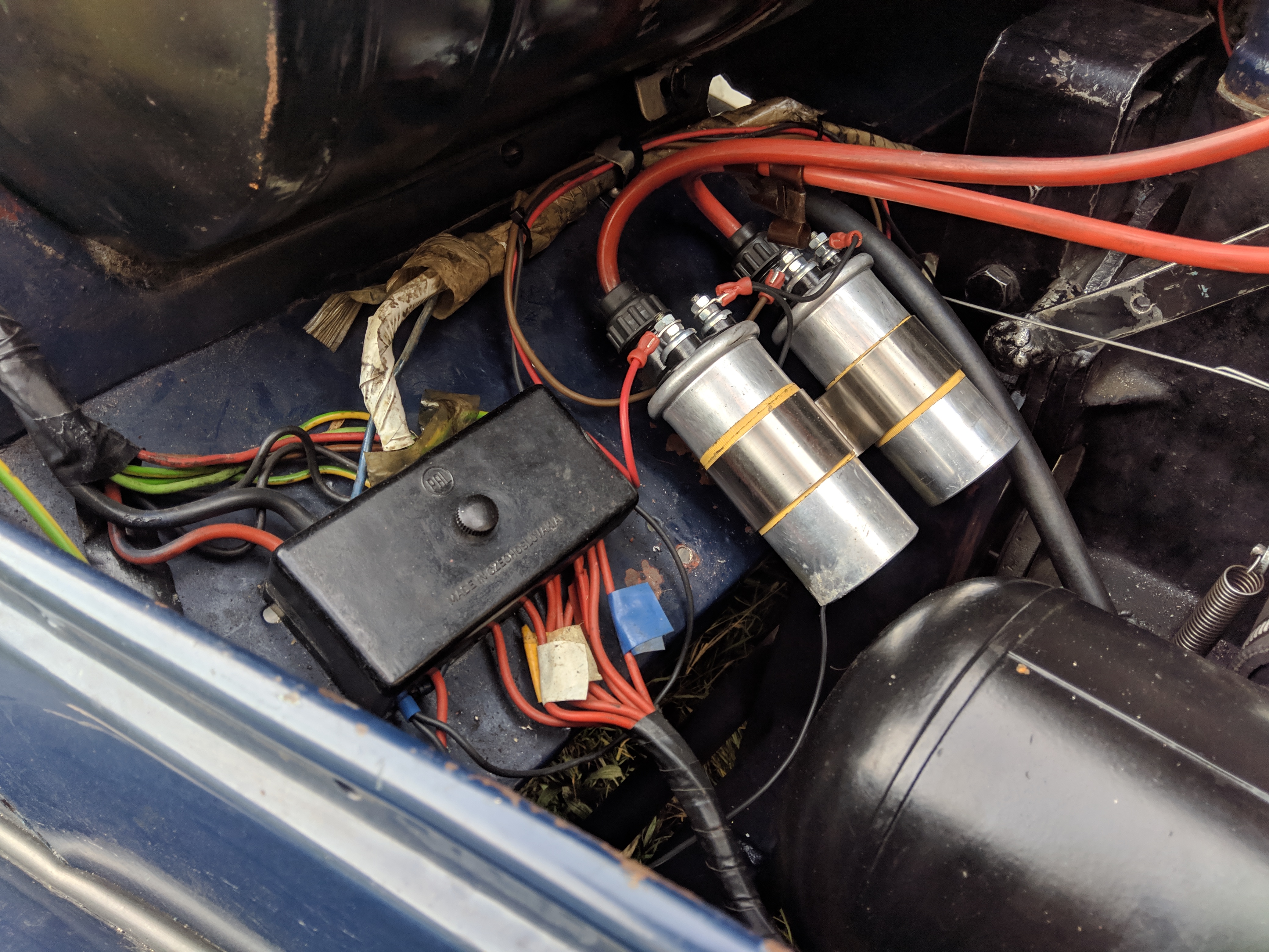
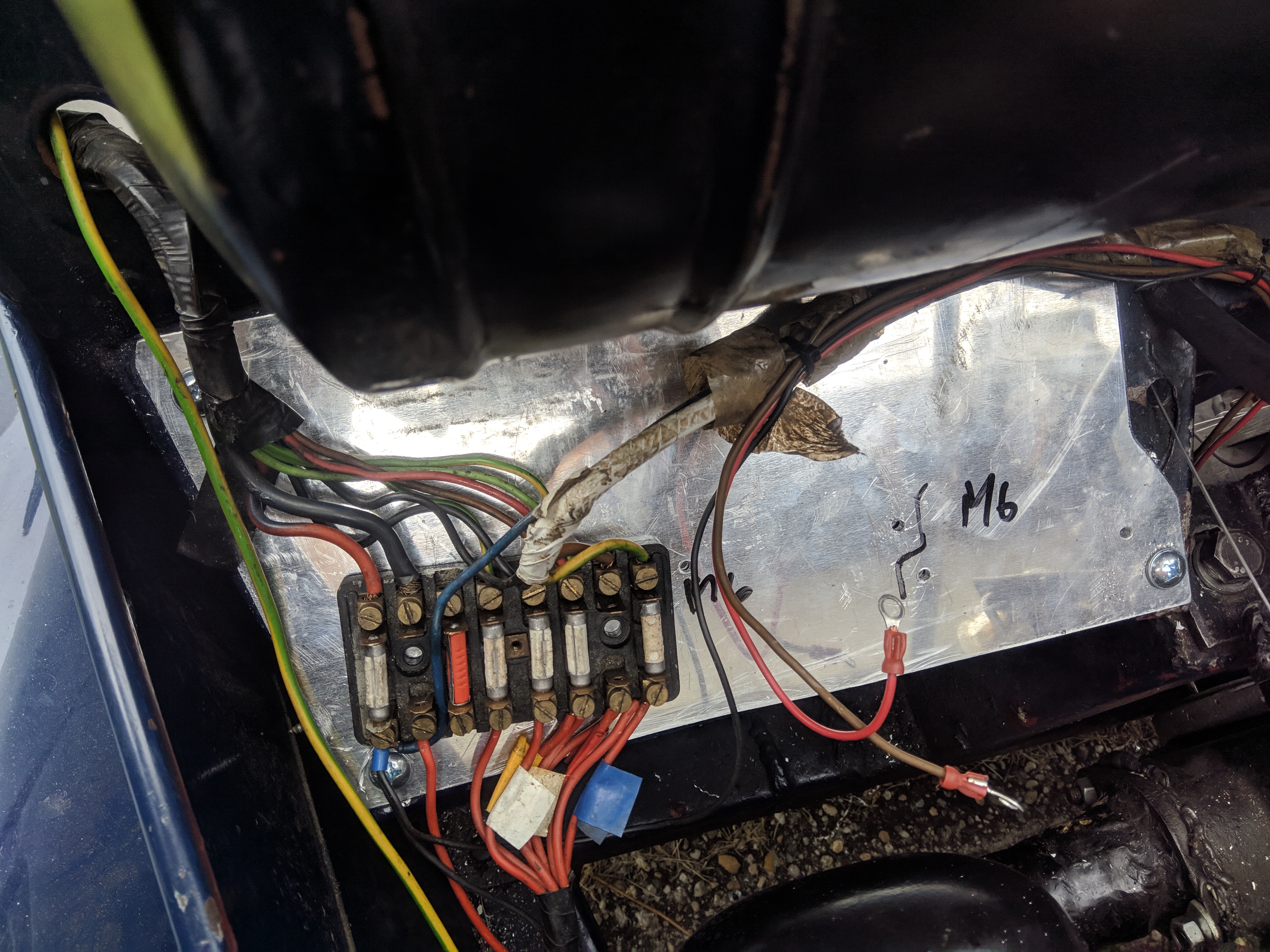
I was not happy with the mounting options that the bulkhead provided, it was in quite a poor condition from many
previous electrical components
being mounted and removed over the years. I mounted an aluminium plate over it and installed riv-nuts into it to mount
the new components.
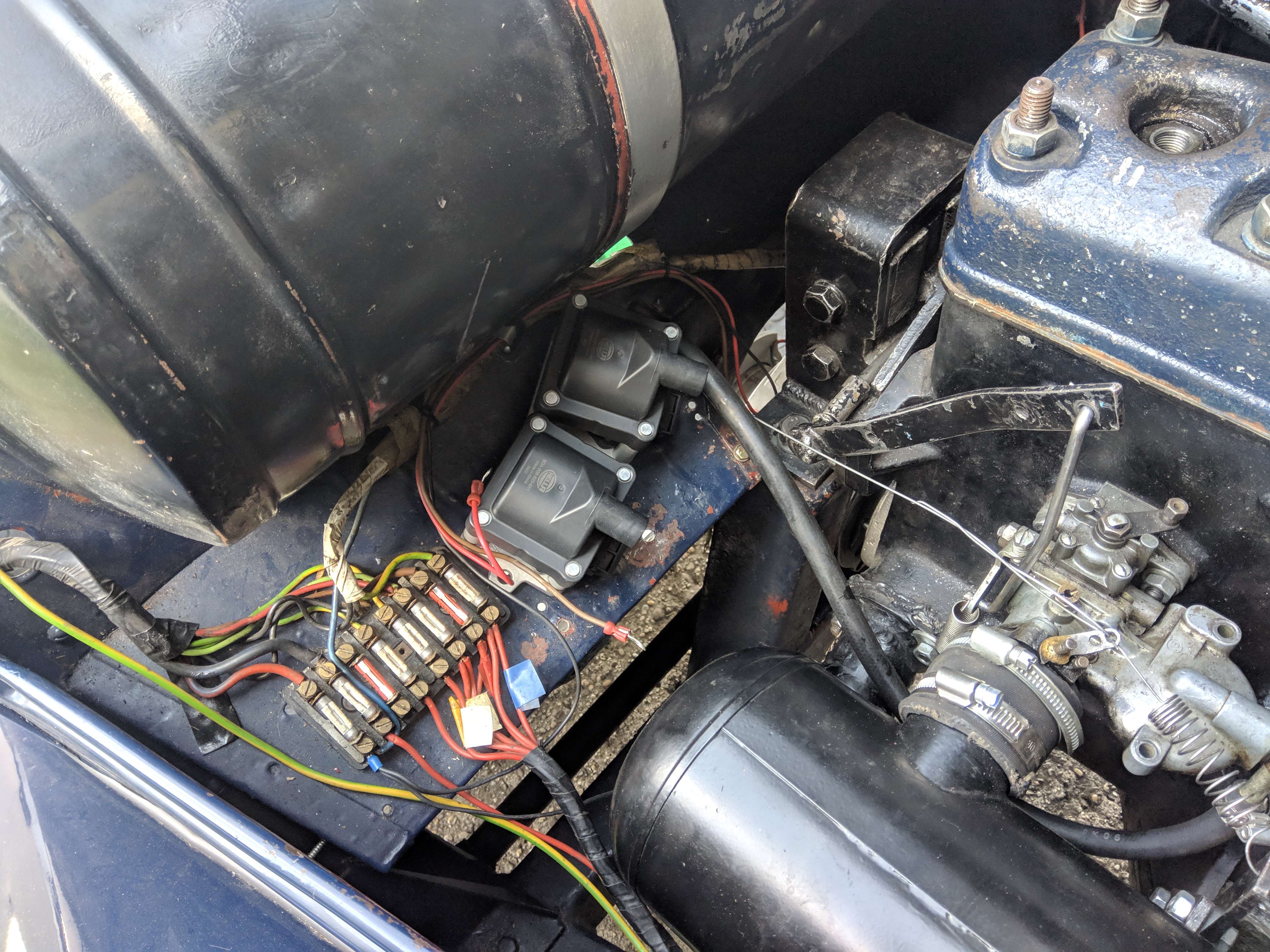
Sadly the old fire hazard of a fuse box was required to stay, it was moved slightly to the side to create
clearance.
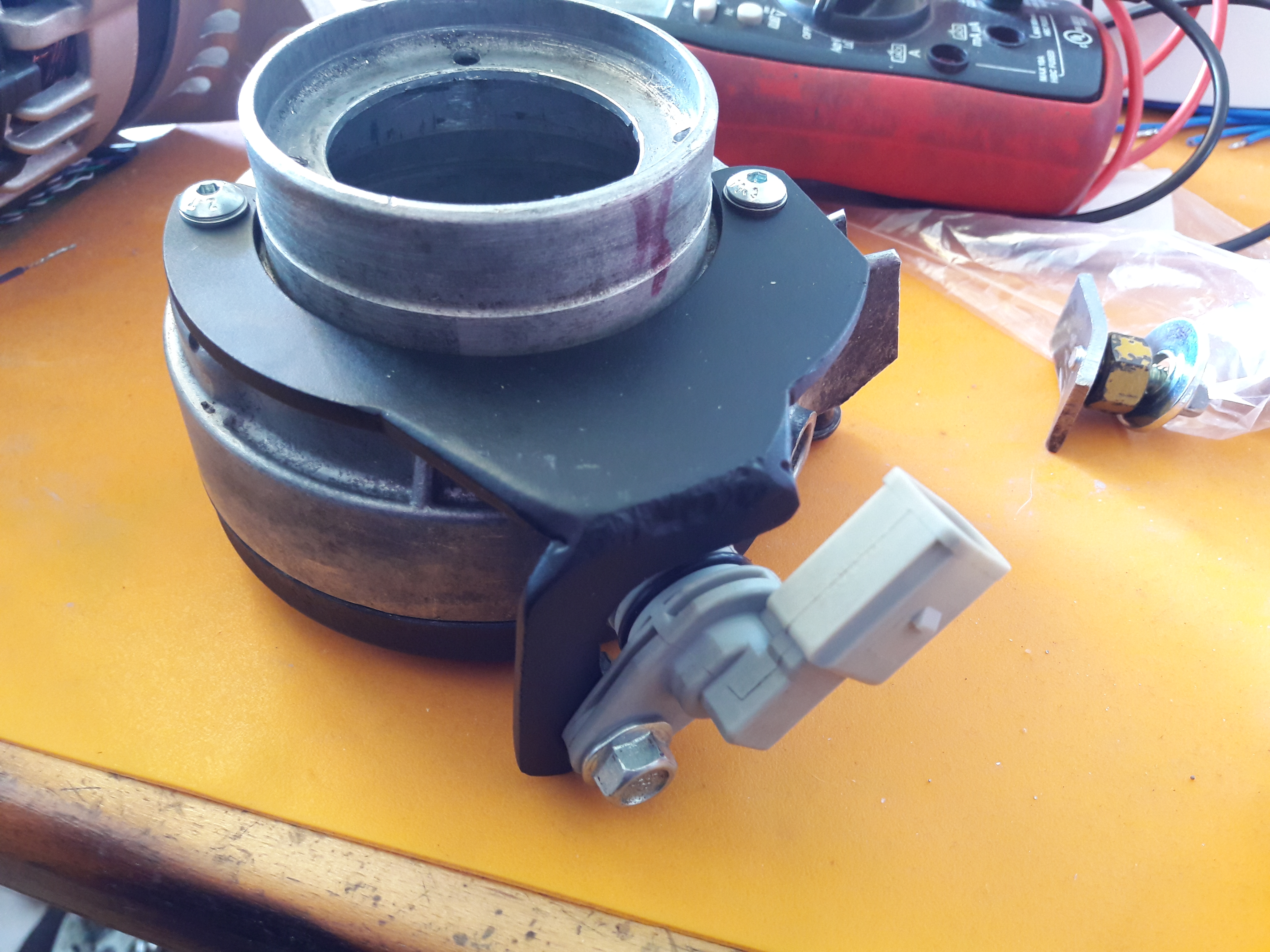
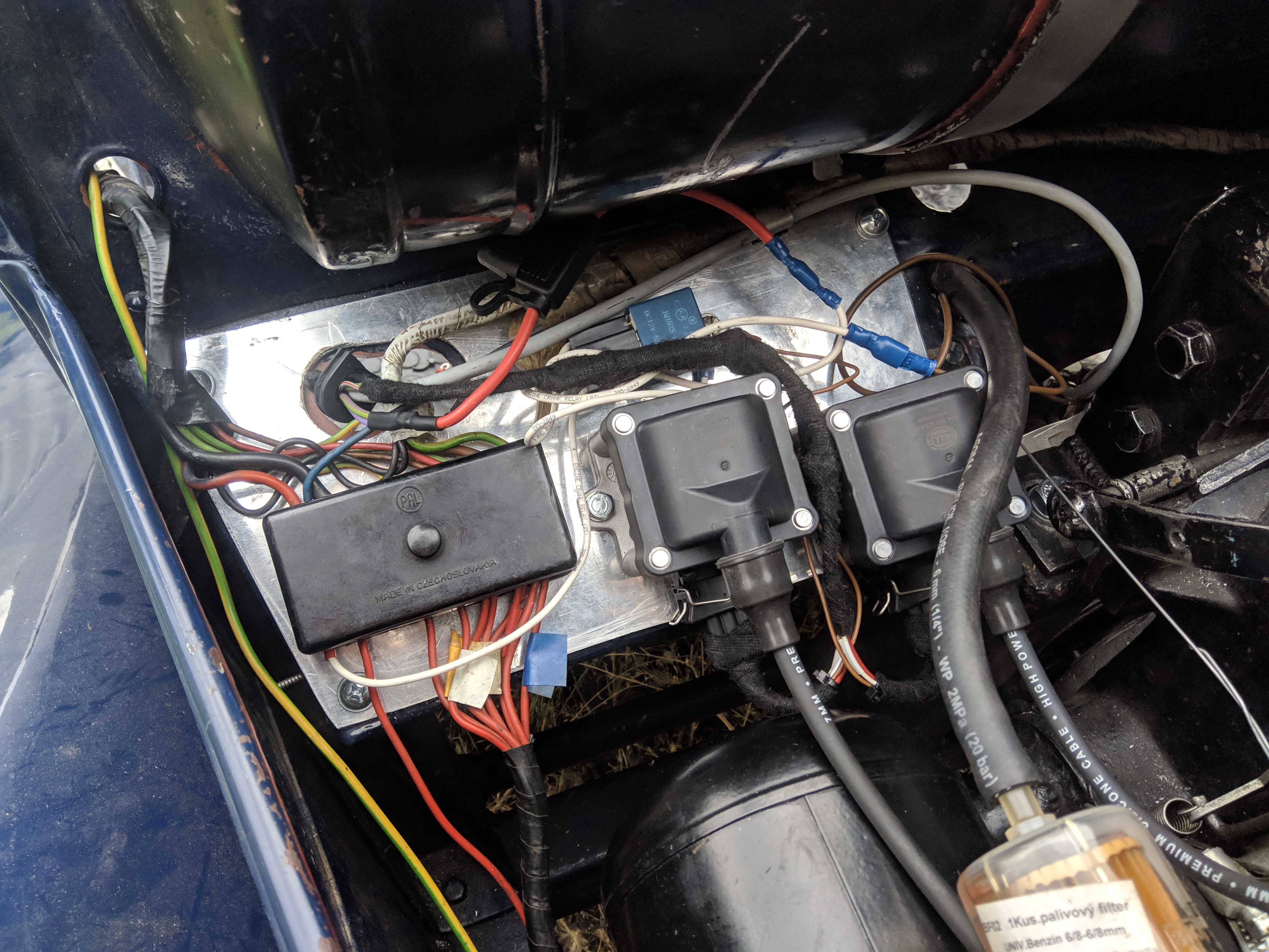
This time the trigger assembly was all complete, with a the full set of painted brackets, and a painted cover.
Due to time constraints of the day no passthrough cover of the harness was made yet and the relay wiring wasn't tidied up
at the time of taking the pictures, so it looks
quite a lot messier than it actually is.
Later I made the passthrough cover, it is clamped from the back by a piece of bar stock.
Page viewed best on a 1600x1200 monitor in Firefox with Terminus font and a dark background